
LED Flashlight

a technology of led flashlights and led flashlights, which is applied in the direction of cell components, lighting and heating apparatus, cell components, etc., can solve the problems of limited distance that the light beam is able to project, current led flashlights typically fail to produce a quality light beam, and existing led flashlights have not provided a reflector/lamp combination that effectively, so as to improve the efficiency of portable lighting devices and improve optical performan

Inactive Publication Date: 2017-10-19
MAG INSTR INC
View PDF15 Cites 0 Cited by
  • Summary
  • Abstract
  • Description
  • Claims
  • Application Information

AI Technical Summary

Benefits of technology

The present invention is about a portable lighting device with better optical performance and higher efficiency. It has a reflector with a parabolic profile and focus located outside the profile, which helps to collimate brighter light rays from the light source. The light source is held relative to the reflector in a variable position. The invention also includes a unique energy source assembly that holds batteries in a side-by-side arrangement. The technical effects of this invention are improved optical performance and more efficient use of light, making it easier to produce a high-quality beam of light.

Problems solved by technology

For example, current LED flashlights typically fail to produce a quality light beam that projects for any appreciable distance.
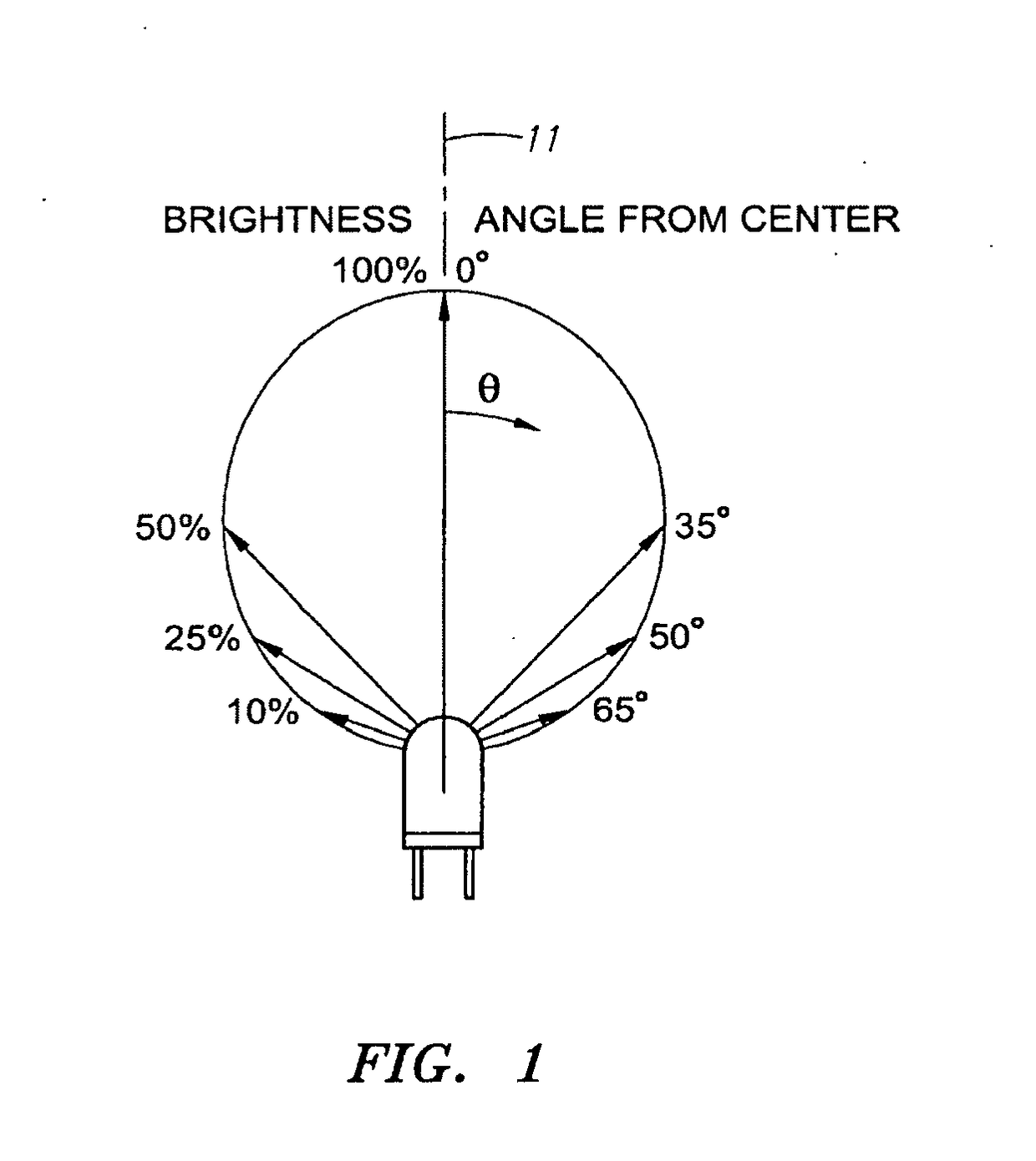
Existing LED flashlights have not provided a reflector / lamp combination that effectively captures the brighter light rays that are concentrated about the center axis.
Accordingly, although available LED lighting devices may be suitable to illuminate the immediate surrounding area, the distance that the light beam is able to project has been limited.
However, such devices involve greater complexity, consume more energy, and cost more to manufacture.
Also, as improvements are made to light sources, such as LEDs, another problem challenging the operation of portable lighting devices is effectively dissipating the increased heat that is generated by the light source.

Method used


Image

  • LED Flashlight
  • LED Flashlight
  • LED Flashlight

Examples


Embodiment Construction

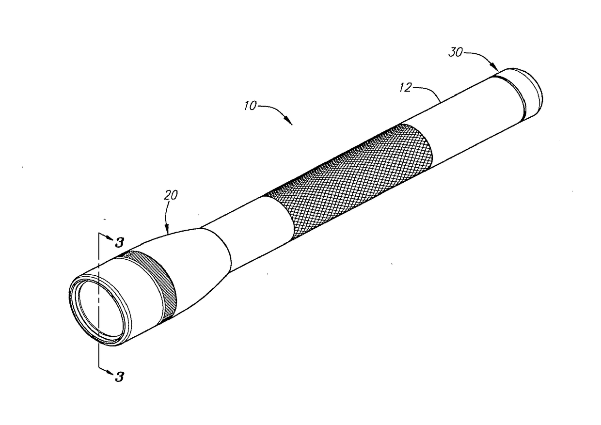
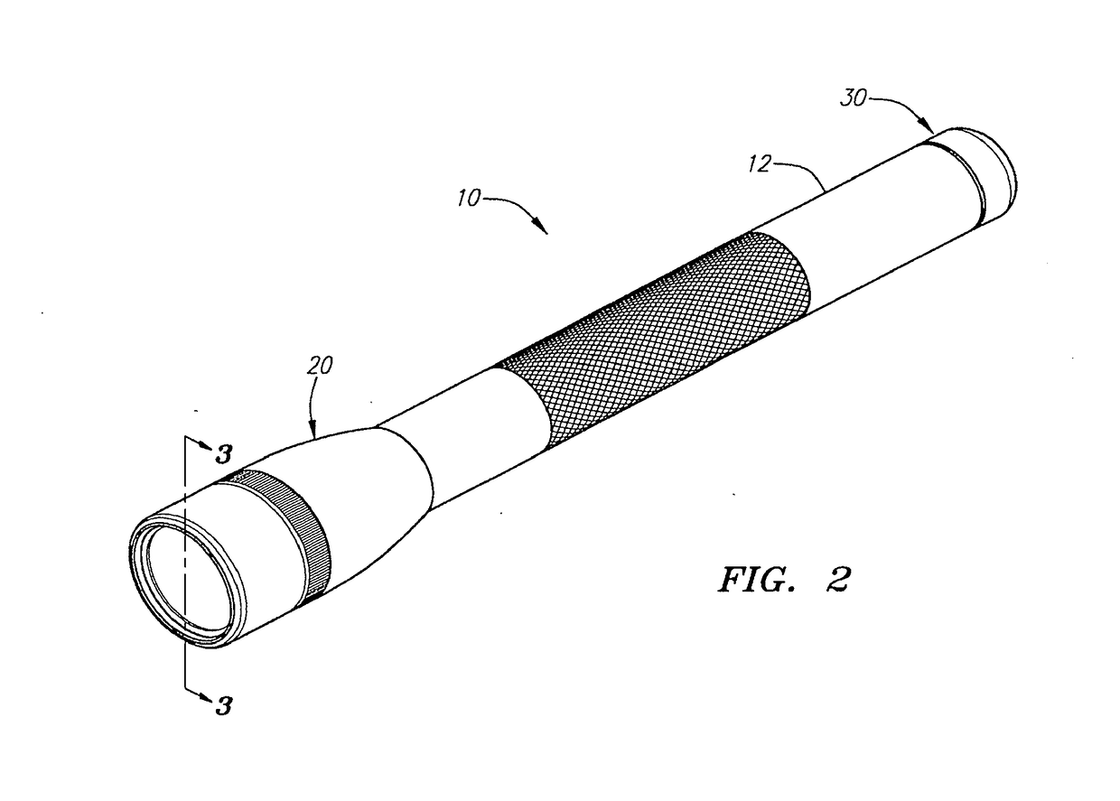
[0031]Referring to FIGS. 2 and 13, a portable lighting device in the form of flashlights 10 and 200, each an embodiment of the present invention, are illustrated in perspective. Each of flashlight 10 and flashlight 200 incorporates various features of the present invention. These features are described in detail below and illustrated in the accompanying figures for the purpose of illustrating the preferred embodiment of the invention. It is to be expressly understood, however, that the present invention is not restricted to the flashlights described herein. Rather, the present invention includes lighting devices that incorporate one or more of the various features of the invention. It is also to be understood that the present invention is directed to each of the inventive features of the lighting devices described below.

[0032]Referring to FIGS. 2 and 3, the flashlight 10 includes a head assembly 20, a barrel 12, a light source 14 and a tail cap assembly 30. The head assembly 20 and ...


PUM

PropertyMeasurementUnit
angleaaaaaaaaaa
spherical angleaaaaaaaaaa
θaaaaaaaaaa

Abstract

A lighting device with improved optical performance and efficiency is provided. The lighting device includes a source of energy, a light source, a reflector and a holder. The reflector has a first open end, a second end, and a parabolic profile extending between the first open end and second end. The focus of the parabolic profile is located outside of the profile. The reflector may also be movable relative to the light source. The lighting device may include a circuit that delivers a pulsed or thermally compensated pulsed current to the light source. The light device may also include a heat sink housing.

Description

CROSS-REFERENCE TO RELATED APPLICATION[0001]The application is a divisional application of application Ser. No. 14 / 287,176, filed May 26, 2014, which is a continuation of application Ser. No. 10 / 922,714, filed Aug. 20, 2004, now U.S. Pat. No. 8,733,966, issued May 14, 2014, the contents of all of which are incorporated by reference as if fully set forth herein.FIELD OF THE INVENTION[0002]The field of the present invention relates to handheld or portable lighting devices, including flashlights and flashlight components.BACKGROUND OF THE INVENTION[0003]Light emitting diodes (“LEDs”) have been used in various applications including illuminating watches, transmitting information from remote controls, and forming images on jumbo television screens. More recently, LEDs have been used in portable lighting devices, such as flashlights, because, among other things, LEDs can last longer and can be more durable than incandescent lamps commonly used in conventional flashlights.[0004]Notwithstan...

Claims


Application Information

Patent Timeline
Patent Type & Authority Applications(United States)
IPC IPC(8): F21V7/06F21V31/00F21V14/04F21V13/04F21V5/04F21V3/00F21L4/00H05B33/08F21V29/70H01M50/519H05B44/00
CPCF21V7/06F21L4/00F21V14/045F21V29/70F21V13/045F21V31/005F21V5/04F21V3/00H05B33/089F21L4/027F21Y2115/10F21V29/507H05B45/56H05B45/395Y02B20/30F21L4/04F21V23/0428
Inventor MAGLICA, ANTHONYWEST, STACEYO'FARRELL, JOHN K.
Owner MAG INSTR INC
Learn More