
Electrical connector with positive lock

a technology of positive locking and electric connectors, applied in the direction of coupling device connections, coupling protective earth/shielding arrangements, electrical apparatus, etc., can solve the problems of data transmission loss, inadvertent separation of plugs from receptacles, etc., and achieve the effect of preventing inadvertent disconnection of two connectors

Active Publication Date: 2006-09-28
AMPHENOL CORP
View PDF6 Cites 68 Cited by
  • Summary
  • Abstract
  • Description
  • Claims
  • Application Information

AI Technical Summary

Benefits of technology

[0003] Accordingly, an object of the present invention is to provide an electrical connector with a positive locking feature that releaseably locks the connector with a mating connector and prevents inadvertent disconnection of the two connectors.

Problems solved by technology

However, these spring arms often fail to sufficiently hold the plug in the receptacle resulting in inadvertent separation of the plug from the receptacle and loss of data transmission.

Method used


Image

  • Electrical connector with positive lock
  • Electrical connector with positive lock
  • Electrical connector with positive lock

Examples


Embodiment Construction

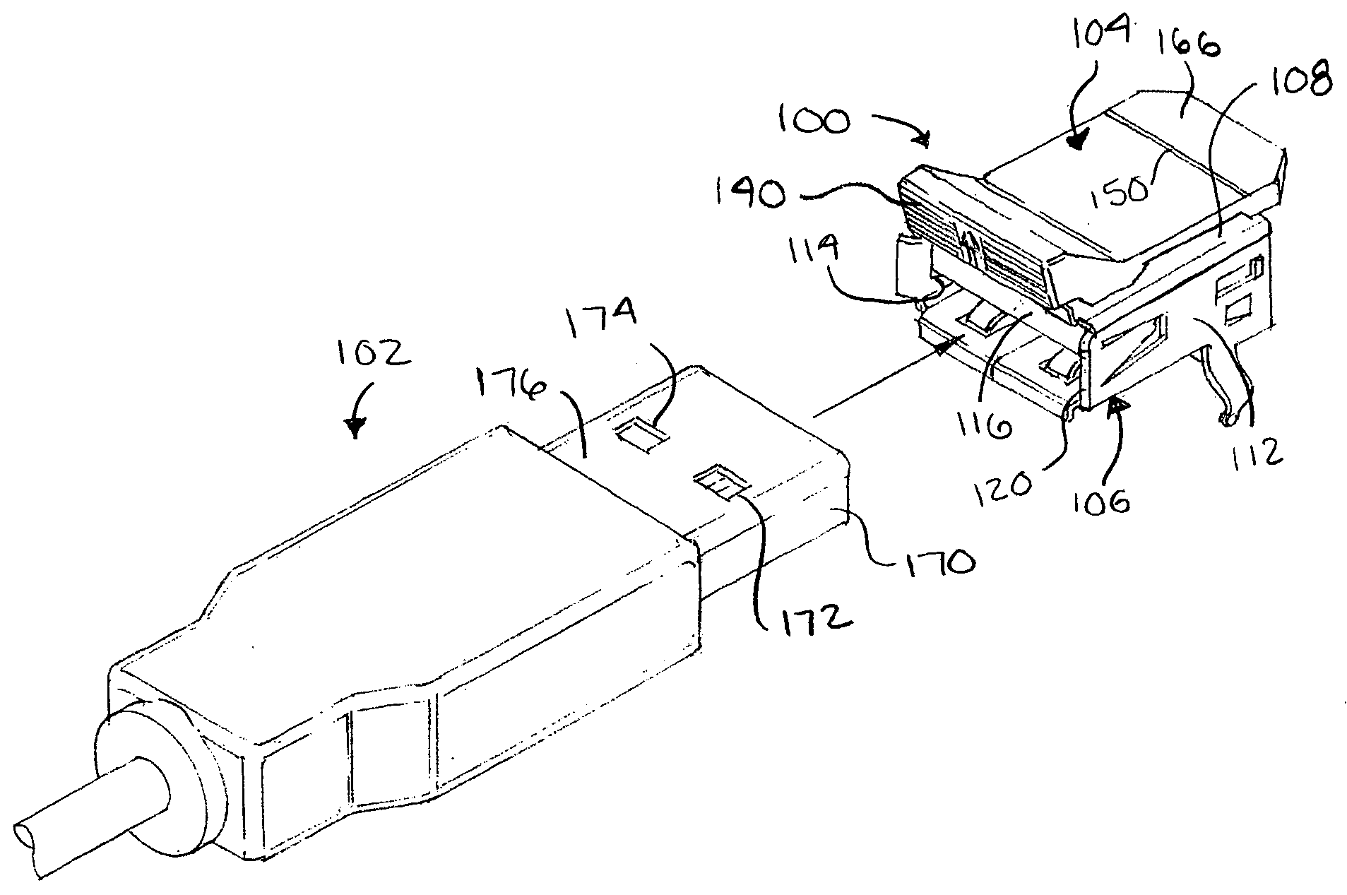
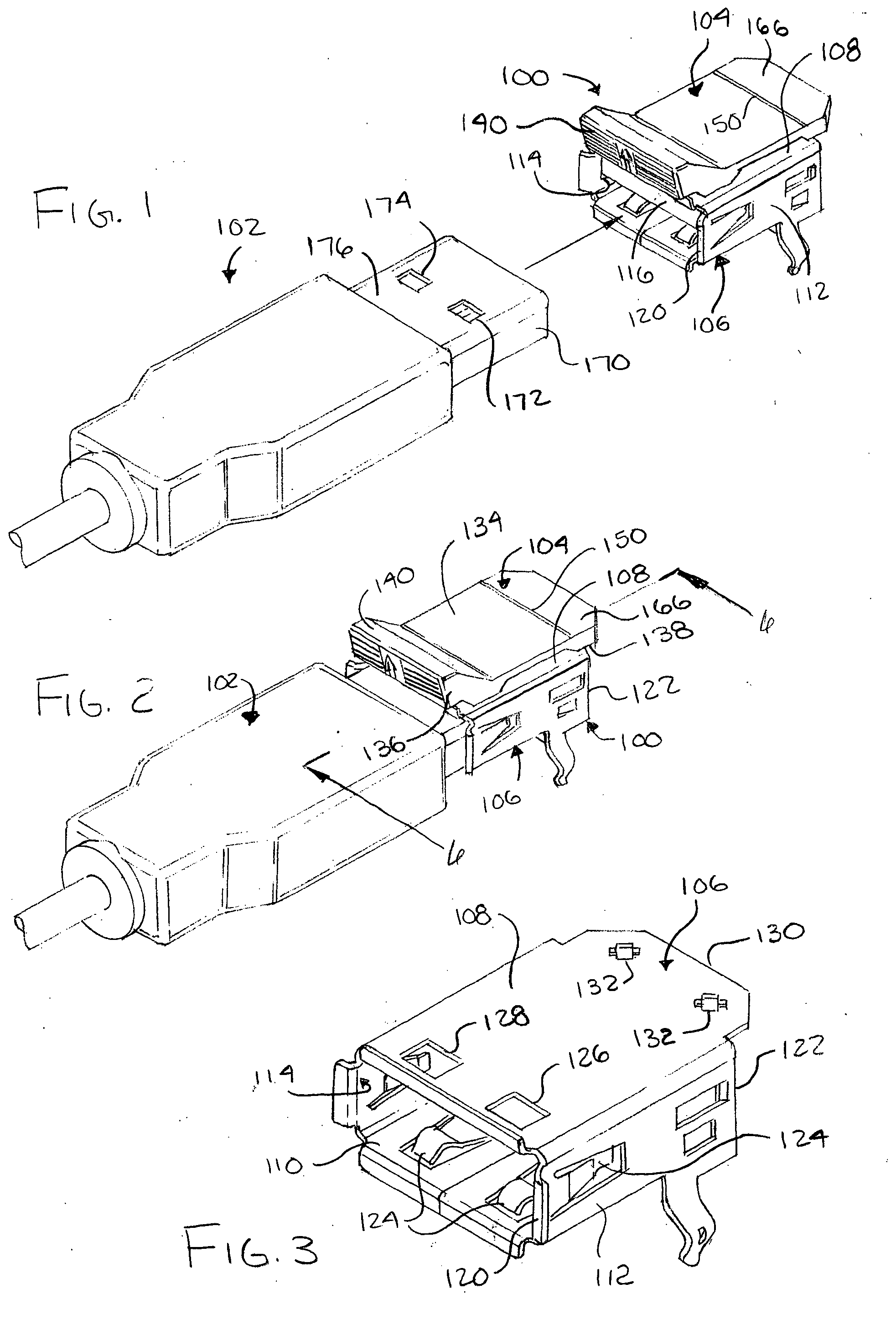
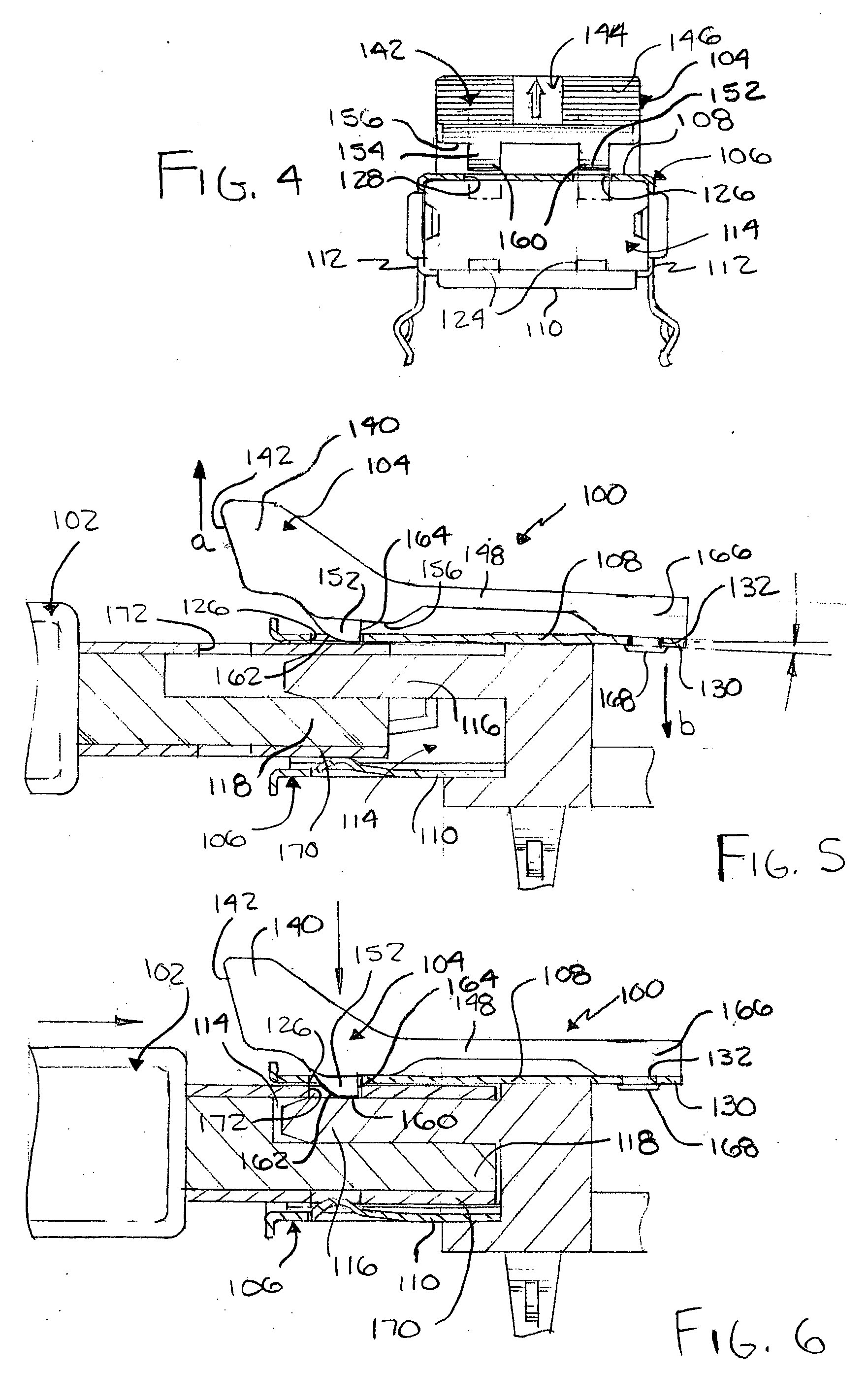
[0015] Referring to FIGS. 1-6, an electrical connector 100 in accordance with the present invention includes a positive locking feature to releasably lock the electrical connector 100, such as a receptacle, with a mating electrical connector 102, such as a plug. In general, the positive locking feature of the electrical connector 100 includes a flexible locking member 104 coupled to the connector 100 that releasably engages the mating connector 102 when the two connectors 100 and 102 are mated. The two connectors 100 and 102 can only be disconnected by releasing the locking member 104 (unless excessive force is used to separate the connectors), thereby preventing inadvertent separation of the two connectors 100 and 102.

[0016] Connector 100 includes a shell 106 with first and second opposite main walls 108 and 110, and sidewalls 112 extending between first and second main walls 108 and 110, as best seen in FIG. 3. Main walls 108 and 110 and sidewalls 112 define an inner area 114 of ...


PUM


Abstract

An electrical connector including a shell having a inner area supporting a contact member adapted to mate with a contact of another connector. The shell includes a wall having at least one locking opening and a flexible extension. A locking member includes first and second ends, the first end including at least one locking tab received in the locking opening and extending into the inner area of the shell in a locked position, and the second end being coupled to the extension of the shell. The locking member is moveable to an unlocked position in a first direction away from the wall of the shell and the extension is moveable in a second direction opposite the first direction, so that no portion of the locking tab extends into the inner area of the shell.

Description

FIELD OF THE INVENTION [0001] The present invention relates to an electrical connector with a positive locking feature for releasably locking the electrical connector to another mating electrical connector. BACKGROUND OF THE INVENTION [0002] Conventional electrical connectors for data transmission, such as universal serial bus (USB) connectors, include two mating parts, a plug and a receptacle. The receptacle receives the plug thereby connecting their respective electrical contacts of the plug and receptacle. Springs arms typically are provided in the receptacle body to grip the plug when it is inserted into the receptacle. However, these spring arms often fail to sufficiently hold the plug in the receptacle resulting in inadvertent separation of the plug from the receptacle and loss of data transmission. SUMMARY OF THE INVENTION [0003] Accordingly, an object of the present invention is to provide an electrical connector with a positive locking feature that releaseably locks the con...

Claims


Application Information

Patent Timeline
Patent Type & Authority Applications(United States)
IPC IPC(8): H01R13/648
CPCH01R13/6275H01R13/65802H01R12/721H01R13/6582
Inventor BOUTROS, KAMAL S.
Owner AMPHENOL CORP
Learn More