Color changer for powder coating system with remote activation

a technology of powder coating system and color changer, which is applied in the direction of burners, combustion types, combustion processes, etc., can solve the problems of time and laborious change or material change operations, and therefore are a significant cost factor

Inactive Publication Date: 2006-10-05
NORDSON CORP
View PDF75 Cites 8 Cited by
  • Summary
  • Abstract
  • Description
  • Claims
  • Application Information

AI Technical Summary

Benefits of technology

[0005] A first inventive aspect contemplates a powder coating material application system having a material changer function for a color change operation. The changer function allows for material flow in one direction and a purge flow in an opposite direction. In one embodiment, a material changer is provided that has a common feed passage connected to a plurality of material supplies, with each supply having an associated inlet passage that opens to the common passage at a port that is sealed by a valve member. The valve member seals the port with a near bore line seal. In a particular embodiment the port is formed in the wall that defines the common feed passage. In a further embodiment the valve member is inflatable by air pressure and a portion of the valve member slightly protrudes into the common feed passage, in effect creating a “zero cavity” or near bore line seal. The common feed passage can be reverse purged with all of the inlet valves closed to an outlet that may be connected to a waste receptacle or other powder collector such as the spray booth. An optional forward purge function may also be used.

Problems solved by technology

These color change or material change operations are time and labor intensive and therefore are a significant cost factor.

Method used


Image

  • Color changer for powder coating system with remote activation
  • Color changer for powder coating system with remote activation
  • Color changer for powder coating system with remote activation

Examples


Embodiment Construction

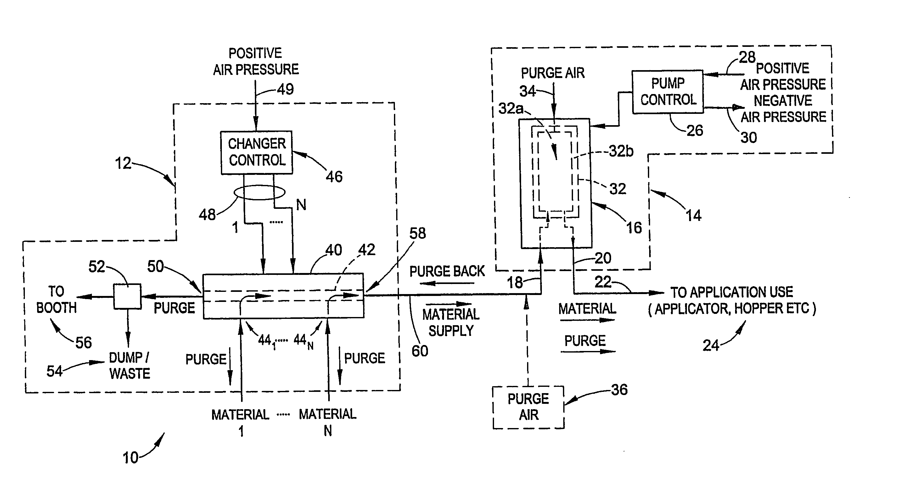
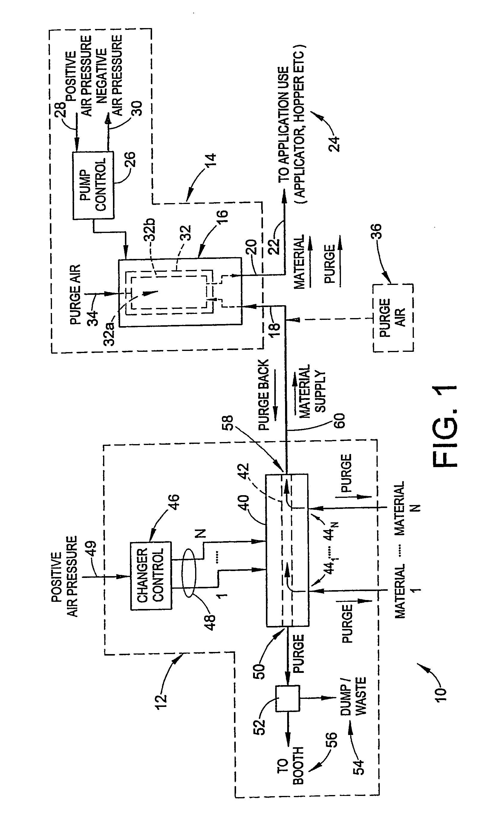
[0023] The embodiments are described herein with particular reference to a material application system, such as for example may be used for the application of powder coating materials such as paint, lacquers and so on. While the described embodiments are presented in the context of a powder coating material application system, those skilled in the art will readily appreciate that the inventive aspects and concepts may additionally be used in many different dry particulate material application systems, including but not limited in any manner to: talc on tires, super-absorbents such as for diapers, food related material such as flour, sugar, salt and so on, desiccants, release agents, and pharmaceuticals. These examples are intended to illustrate the broad application of the inventions for application of particulate material to objects or surfaces. The specific design and operation of the material application system selected provides no limitation on the present inventions except as o...


PUM


Abstract

A material or color changer has a common feed passage that is connected to two or more inlet passages. The common feed passage can be reverse purged in a direction that is opposite a direction of powder flow through the common feed passage. A valve element seals a supply port that connects the inlet passage to the common feed passage to eliminate dead space and form a near bore line seal. The valve element is an elastic material that expands in response to applied compressed air inside the valve element. A remote activation function may be provided to facilitate initiating a color change procedure. In one embodiment, the remote activation function may be a pneumatic foot switch, while in another embodiment it may be an electrical switch, such as a membrane switch for example, mounted on a spray gun.

Description

RELATED APPLICATIONS [0001] This application is a Continuation in Part of pending U.S. patent application Ser. No. 11 / 144,878 filed on Jun. 3, 2005 for COLOR CHANGE FOR POWDER COATING MATERIAL APPLICATION SYSTEM, which claims the benefit of U.S. Provisional patent application Ser. No. 60 / 577,223 filed on Jun. 3, 2004 for AUTOMATED POWDER COLOR CHANGE SYSTEM, the entire disclosures of which are fully incorporated herein by reference. This application also claims the benefit of U.S. Provisional patent application Ser. No. 60 / 718,492 filed on Sep. 19, 2005, for COLOR CHANGER FOR POWDER COATING SYSTEM WITH FOOT SWITCH, the entire disclosure of which is fully incorporated herein by reference.TECHNICAL FIELD OF THE INVENTIONS [0002] The inventions relate generally to material application systems, such as for example powder coating material application systems, and more particularly to apparatus and methods for improved material change operations such as for example quick color change. BAC...

Claims


Application Information

Patent Timeline
Patent Type & Authority Applications(United States)
IPC IPC(8): B05B15/02A62C31/00A62C5/00
CPCB05B7/1404B05B7/1459B05B15/1229B05B12/149B05B7/1477B05B14/48
Inventor FULKERSON, TERRENCE M.THOMPSON, TERRY JOHNDAILIDAS, JEFFERY EDWARDKREEGER, KENNETH A.SCHROEDER, JOSEPH G.
Owner NORDSON CORP
Why Eureka
Try Eureka