Light emitting diode current control method and system

a technology of current control and light-emitting diodes, which is applied in the direction of electric variable regulation, process and machine control, instruments, etc., can solve the problems of power source, no assurance, and unwanted flicker

Inactive Publication Date: 2006-10-05
NEXXUS LIGHTING
View PDF4 Cites 74 Cited by
  • Summary
  • Abstract
  • Description
  • Claims
  • Application Information

AI Technical Summary

Benefits of technology

[0007] A dynamic power management system for a point source LED having three or more colored LED sources wherein an LED manufacturing process requires that a maximum allowed current through each LED be dependent upon a total current supplied to all LED sources is also disclosed. Th...

Problems solved by technology

One drawback with amplitude modulation is that there is a time interval during which the LED does not illuminate because the voltage is at a low end of the voltage range, below the forward conduction voltage.
Another drawback is that typically there is no assurance that two identical LEDs, even though produced by the same manufacturer, will provide the same output of light for a given voltage since the manufacturing...

Method used


Image

  • Light emitting diode current control method and system
  • Light emitting diode current control method and system
  • Light emitting diode current control method and system

Examples


Embodiment Construction

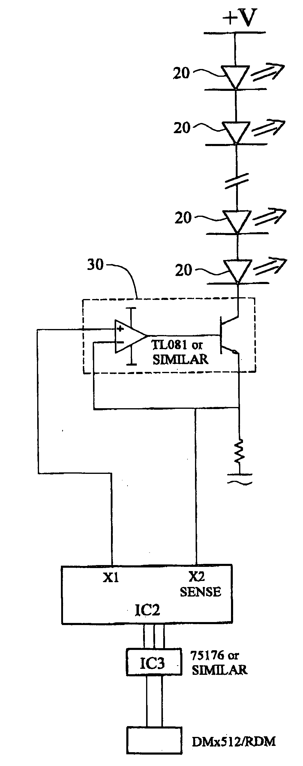
[0013] Before proceeding to a detailed description of preferred embodiments of the present invention and alternate embodiment, several general comments should be made about the applicability and the scope of the present invention. The present invention can be implemented through hardware and / or software. Though several illustrations discuss the present invention being used with multiple LEDs and in some illustrations a single LED, the present invention can also be used with either a single LED as well as multiple LEDs. Likewise, though some elements are identified as either singular or as a plurality, the reverse of each identification is also possible.

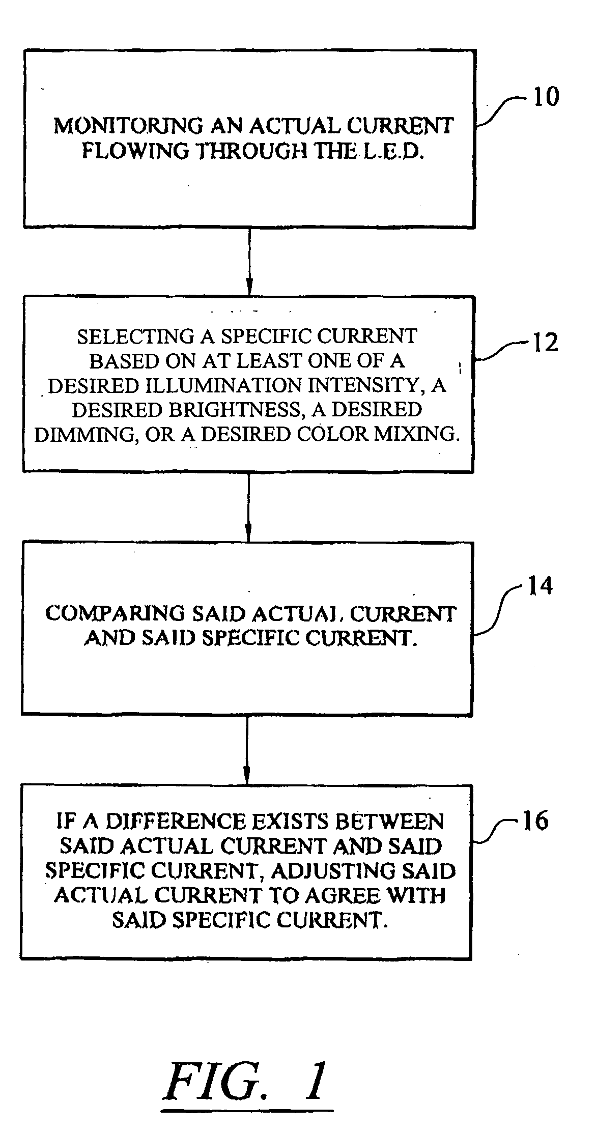
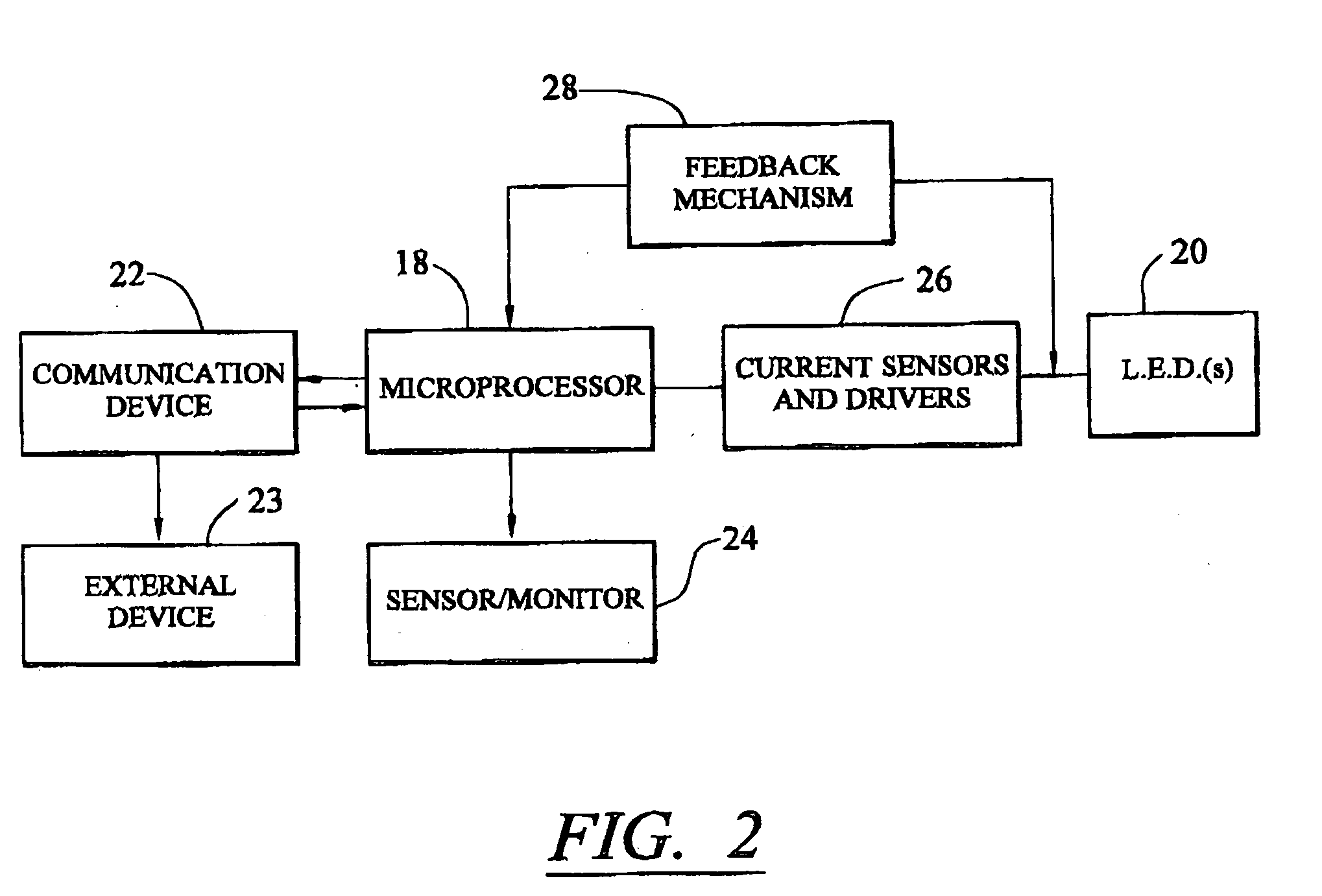
[0014] Referring initially to FIGS. 1 and 2, a system and procedure for controlling illumination intensity in an LED are illustrated. FIG. 1 is an exemplary embodiment of a flow chart illustrating a method of the present invention. As illustrated, an actual current level is monitored across an LED 20 at step 10. The measurement, for ...


PUM


Abstract

A method of accurately controlling at least one of an intensity, brightness, dimming or color mixing of a LED, the method comprising monitoring an actual current flowing through the LED, selecting a specific current based on at least one of a desired illumination intensity, a desired brightness, a desired dimming, or a desired color mixing, comparing said actual current and said specific current, and if a difference exists between said actual current and said specific current, adjusting said actual current to agree with said specific current.

Description

BACKGROUND OF THE INVENTION [0001] The present invention relates to a lighting system, and more particularly to a light emitting diode (LED) lighting system and method where illuminated intensity of the LED is controlled by varying current applied to the LED. [0002] There are a number of techniques that can be used to control illumination intensity of an LED. One such technique is to vary the voltage that flows across the LED, otherwise known as amplitude modulation. This is accomplished with a current limiting resistor positioned in the circuit. As the voltage is increased, the LED will start to illuminate when the voltage exceeds a forward conduction voltage of the LED. Increased voltage will then increase the intensity of the LED. One drawback with amplitude modulation is that there is a time interval during which the LED does not illuminate because the voltage is at a low end of the voltage range, below the forward conduction voltage. Another drawback is that typically there is ...

Claims


Application Information

Patent Timeline
IPC IPC(8): H05B37/00
CPCH05B33/0812Y02B20/345H05B33/0842H05B45/395Y02B20/30H05B45/24H05B45/28
Inventor HOWELL, WAYNEHOBDAY, SIMONBRADFORD, ALLANPULLEY, ADAMKVIST, CRISTOFFERFABER, STEPHEN M.KINGSTONE, BRETT
Owner NEXXUS LIGHTING
Why Eureka
Try Eureka