Lighting device having a circuit including a plurality of light emitting diodes, and methods of controlling and calibrating lighting devices

a technology of light emitting diodes and lighting devices, which is applied in the direction of lighting and heating apparatus, lighting source combinations, instruments, etc., can solve the problems of increasing the cost of the circuit, inefficient circuits that have been used to drive led lighting devices, and potentially damaging leds and other circuit components

Inactive Publication Date: 2006-10-12
SC JOHNSON & SON INC
View PDF35 Cites 147 Cited by
  • Summary
  • Abstract
  • Description
  • Claims
  • Application Information

AI Technical Summary

Benefits of technology

The invention is a lighting device that includes a circuit with a power supply and a series of light emitting diodes. The circuit also includes optically isolated field effect transistors that are connected in parallel with each group of light emitting diodes to selectively shunt around them. A controller is connected to the optically isolated field effect transistors to turn them on and off, and a plurality of capacitors is connected in parallel with each optically isolated field effect transistor to smooth the wave form of the supply current. The lighting device also includes a removable memory medium that stores data of at least one program, which the controller controls the light emitting diodes according to. The technical effect of this invention is to provide a lighting device with improved control over the light emitting diodes, which can be programmed to different settings and smooth the wave form of the supply current.

Problems solved by technology

The technical problem addressed in this patent text relates to improving the efficiency and reducing the costs associated with driving LED lights while maintaining their brightness and lifespan. Current methods involve using inefficient resistance and semiconductor components to regulate the voltage needed to activate LEDs, resulting in excessive heat production and potential damage to the LEDs. This has led some researchers to suggest arranging multiple LEDs in series but this approach still results in increased expense and complexity compared to simpler solutions. There is thus a need for a new solution that addresses these issues.

Method used


Image

  • Lighting device having a circuit including a plurality of light emitting diodes, and methods of controlling and calibrating lighting devices
  • Lighting device having a circuit including a plurality of light emitting diodes, and methods of controlling and calibrating lighting devices
  • Lighting device having a circuit including a plurality of light emitting diodes, and methods of controlling and calibrating lighting devices

Examples


Embodiment Construction

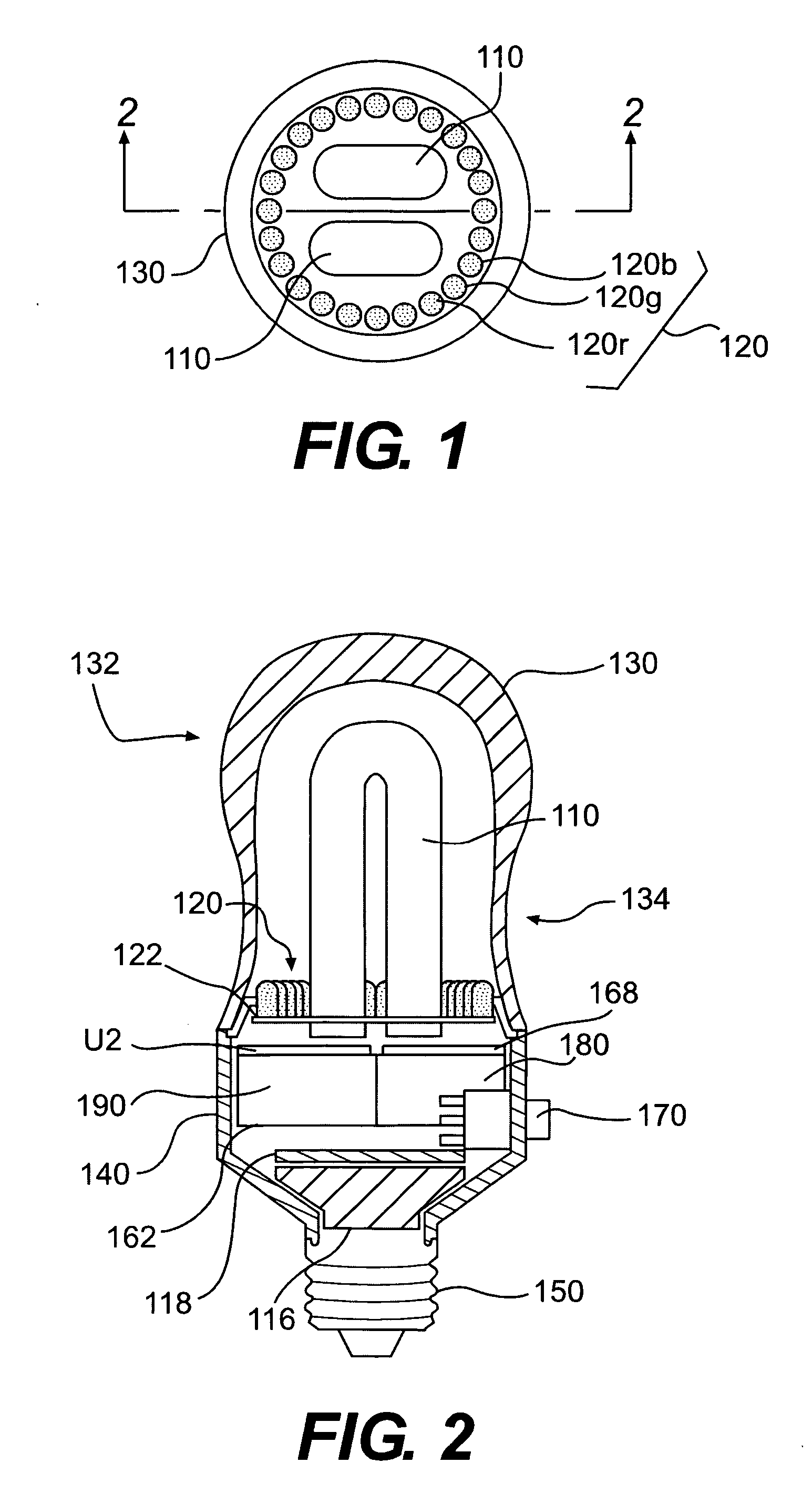
[0029] One preferred lighting device according to our invention is illustrated in FIGS. 1 and 2. In this embodiment, the lighting device comprises an Edison-style light bulb 132 (i.e., a screw-in light bulb configured to mount in a conventional light socket). However, as discussed above, lighting devices according to our invention may take any desired shape and size, and need not be configured as a bulb for engagement with an incandescent light fixture. For example, lighting devices according to our invention also include bulbs for engagement with any standard light fixture (e.g., fluorescent, incandescent, halogen, etc.), as well as stand-alone devices configured to be plugged into a wall socket, and the like.

[0030] As shown in FIGS. 1 and 2, the bulb 132 includes a base 140 having a screw-in connector 150 adapted to mate with a conventional incandescent light socket in a lamp, light fixture, or the like. A plurality of LEDs 120 is mounted on the base 140. Preferably, one or more ...


PUM


Abstract

A lighting device (132) includes a circuit having a power supply and a plurality of light emitting diodes (120) connected in series with the power supply. The plurality of light emitting diodes (120) includes at least two groups of series-connected light emitting diodes, the groups of series-connected light emitting diodes being connected in series. A different optically isolated field effect transistor (U3-U5) is connected in parallel with each group of series-connected light emitting diodes, for selectively shunting around the group of series-connected light emitting diodes. A different capacitor (C8-C10) can also be connected in parallel with each group of series-connected light emitting diodes. A controller (U2) is connected to a gate of each of the optically isolated field effect transistors (U3-U5) for selectively turning the optically isolated field effect transistors (U3-U5) on and off. Thus, the controller U2 is electrically isolated from the power supply by the optically isolated field effect transistors (U3-U5). The light emitting diodes (120) can be driven and controlled using pulse width modulation methods.

Description


Claims


Application Information

Patent Timeline
Owner SC JOHNSON & SON INC
Why Eureka
Try Eureka