Electronic apparatus

a technology of electronic equipment and touch panel, applied in the direction of steering initiation, instruments, vessel construction, etc., can solve the problems of vibration exercise a harmful influence on components, vibration of the touch panel is transmitted to the main body, etc., and achieve the effect of preventing vibration transmission

Active Publication Date: 2006-10-19
NEC PLATFORMS LTD
View PDF6 Cites 66 Cited by
  • Summary
  • Abstract
  • Description
  • Claims
  • Application Information

AI Technical Summary

Benefits of technology

[0009] It is therefore an object of this invention to provide an electrical apparatus capable of preventing transmiss

Problems solved by technology

It is possible that the vibration exercises a harmful influence on components (e.g. a liquid crystal display unit) and circuits housed in th

Method used


Image

  • Electronic apparatus
  • Electronic apparatus
  • Electronic apparatus

Examples


first embodiment

[0025] Referring to FIGS. 1 to 3, a description will be directed to an electronic apparatus according to this invention.

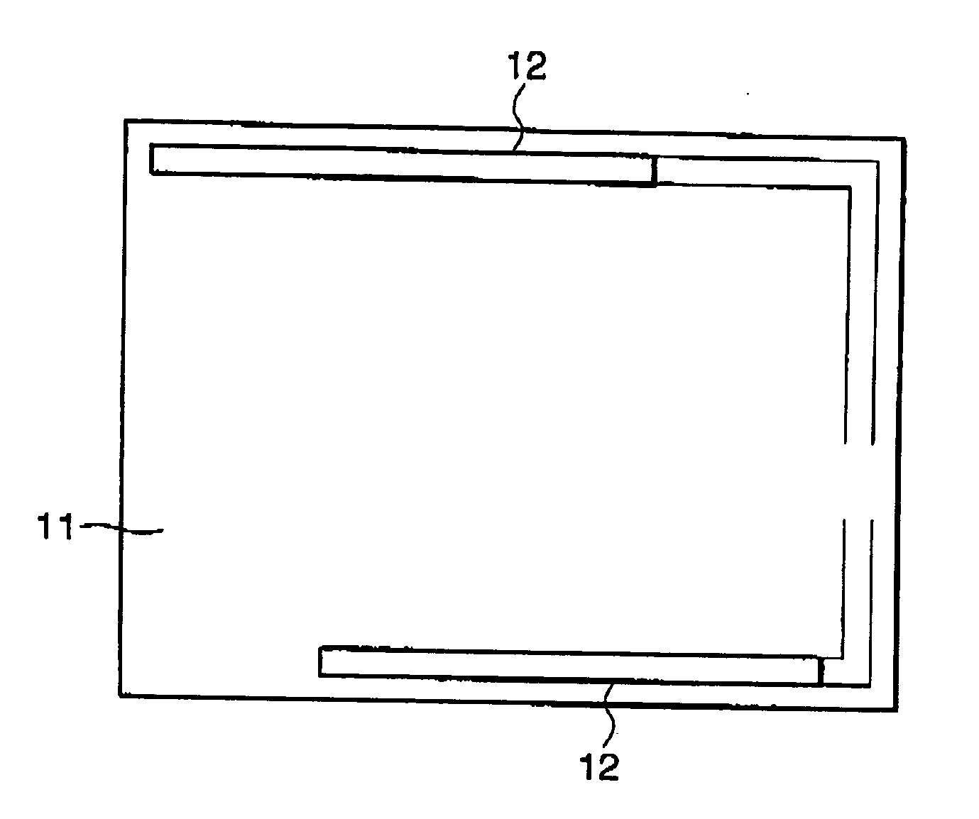
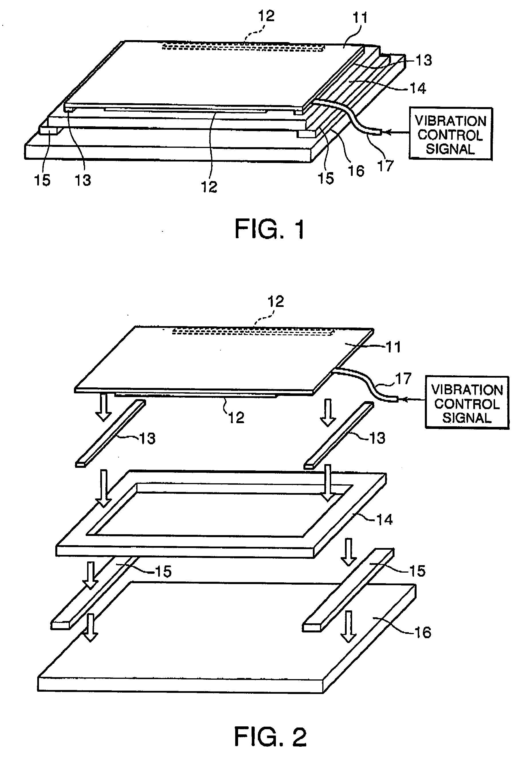
[0026]FIG. 1 is a perspective view of the electronic apparatus (or a panel assembly) of the first embodiment while FIG. 2 is an exploded perspective view thereof.

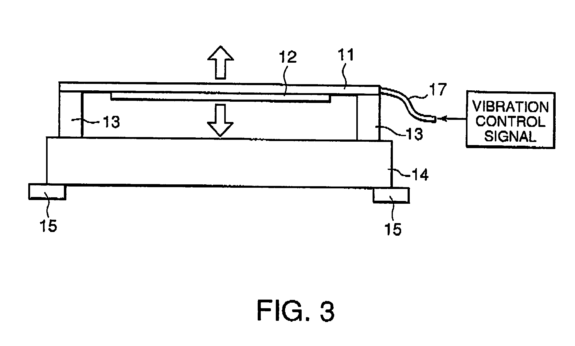
[0027] The electronic apparatus includes a rectangular touch panel (or a flat vibrating body) 11 having a glass or resinous substrate at a rear side thereof. On a rear surface of the touch panel 11, pair of vibrating elements 12 are fixed along upper (or rear side of FIG. 2) and lower (or front side of FIG. 2) edges of the touch panel 11. The rear surface of the touch panel 11 corresponds to an exposed surface of the glass or resinous substrate. Further, on the rear surface of the touch panel 11, pair of fixing cushions 13 are fixed along right and left edges of the touch panel 11. A fixing frame 14 has a frame or rectangular shape, which is nearly equal to or slightly larger than the touch panel 11 in le...

second embodiment

[0039] Next, referring to FIGS. 5 to 7, the description will be made about an electronic apparatus (i.e. a POS terminal) according to this invention.

[0040] The electronic apparatus of FIG. 5 has a display and touch panel portion 51. The display and touch panel portion 51 includes a touch panel 52 with a vibrating function. FIG. 6 is an exploded perspective view of the display and touch panel portion 51. FIG. 7 is a partly sectional view of the display and touch panel portion 51.

[0041] The display and touch panel portion 51 serves as a display unit for displaying information and as an input unit for receiving input data. The display and touch panel portion 51 includes a front bezel 61, vibrating elements 62, fixing cushions 63, a fixing frame 64, pressing cushions 65, a liquid crystal display panel (LCD) 66, vibration absorbing members 67, and a rear cover (or a chassis) 68, in addition to the touch panel 52. A combination of the touch panel 52, the vibrating elements 62, the fixing...


PUM


Abstract

In an electronic apparatus having a touch panel and a chassis for supporting the touch panel, pair of fixing cushions are fixed to the touch panel along edges, which are parallel to each other, of the touch panel. Pair of vibration absorbing cushions are fixed to the chassis parallel to each other. A fixing flame is disposed between the touch panel and the chassis and fixed to the fixing cushions and the vibration absorbing cushions. Thus, the touch panel is supported against the chassis by the fixing cushions, the fixing frame and the vibration absorbing cushions. When the touch panel vibrates, the vibration absorbing cushions prevent transmission of the vibration from the touch panel to the chassis through fixing cushions and the fixing frame. Accordingly, the vibration of the touch panel hardly exercises a harmful influence on components mounted on the chassis.

Description

[0001] This application claims priority to prior application JP 2005-028505, the disclosure of which is incorporated herein by reference. BACKGROUND OF THE INVENTION [0002] This invention relates to an electronic apparatus, particularly, to improvement of an electronic apparatus which is configured so that a flat vibrating body (e.g. a touch panel) is vibrated by a vibrating element(s). [0003] A touch panel is well known as an input device for an electronic apparatus. A type of the touch panel provides a vibrating function to give operation feeling to an operator. [0004] The touch panel having the vibrating function vibrates when its surface is pressed with a finger of the operator, a stylus held by the operator, or the like. The vibration of the touch panel is transmitted to the operator through his / her finger or the like. Thus, the operator perceives whether input operation executed by the operator is accepted by the electronic apparatus or not. [0005] A conventional electronic ap...

Claims


Application Information

Patent Timeline
IPC IPC(8): G09G5/00
CPCG06F3/016G06F1/18B63H9/06B63H25/04B63B41/00B63H2009/082Y02T70/5236
Inventor NISHIMURA, HIDEKIYAMASHITA, SYUNICHI
Owner NEC PLATFORMS LTD
Why Eureka
Try Eureka