
Rotating, sitting-up bed comprising a thigh-raising device

Inactive Publication Date: 2006-10-26
BARTHELT HANS PETER
View PDF10 Cites 18 Cited by
  • Summary
  • Abstract
  • Description
  • Claims
  • Application Information

AI Technical Summary

Benefits of technology

[0005] It is an object of the invention to provide a sitting-up bed that does not cause the patient to feel unsafe in the sitting position even when the bed had reduced sitting depth.
[0006] The novel sitting-up bed according to the invention has a thigh part connected to a center part by means of a hinge such that when the bed is in the sitting position, the seat area of the patient lies approximately above the center part, while the thigh up to the back of the knee lies on the thigh part. Furthermore, means are provided to further lift the thigh part in the vicinity of the back of the knee in the recliner or chair position. In this way, the center part forms a flat depression together with the thigh part. This depression remains even when a mattress material is used that is not suitable for generating such a depression, resulting a feeling of safety to the user when in the sitting position.
[0007] The resulting flat sitting depression, which is bounded behind the patient by the back part, enables the distance between the bend at which the back part transitions into the sitting surface to the bend where the sitting surface is bent downwards at the front edge, to be shortened, without making the patient feel unsafe in the sitting position. On the other hand, the shortened sitting surface considerably simplifies patient transfer from the bed to a wheelchair for the care provider, and without additional mechanical aids.

Problems solved by technology

Decreasing the sitting depth, however, can cause the patient to feel unsafe in a sitting position, especially if the mattress is not made from viscose foam.

Method used


Image

  • Rotating, sitting-up bed comprising a thigh-raising device
  • Rotating, sitting-up bed comprising a thigh-raising device
  • Rotating, sitting-up bed comprising a thigh-raising device

Examples


Embodiment Construction

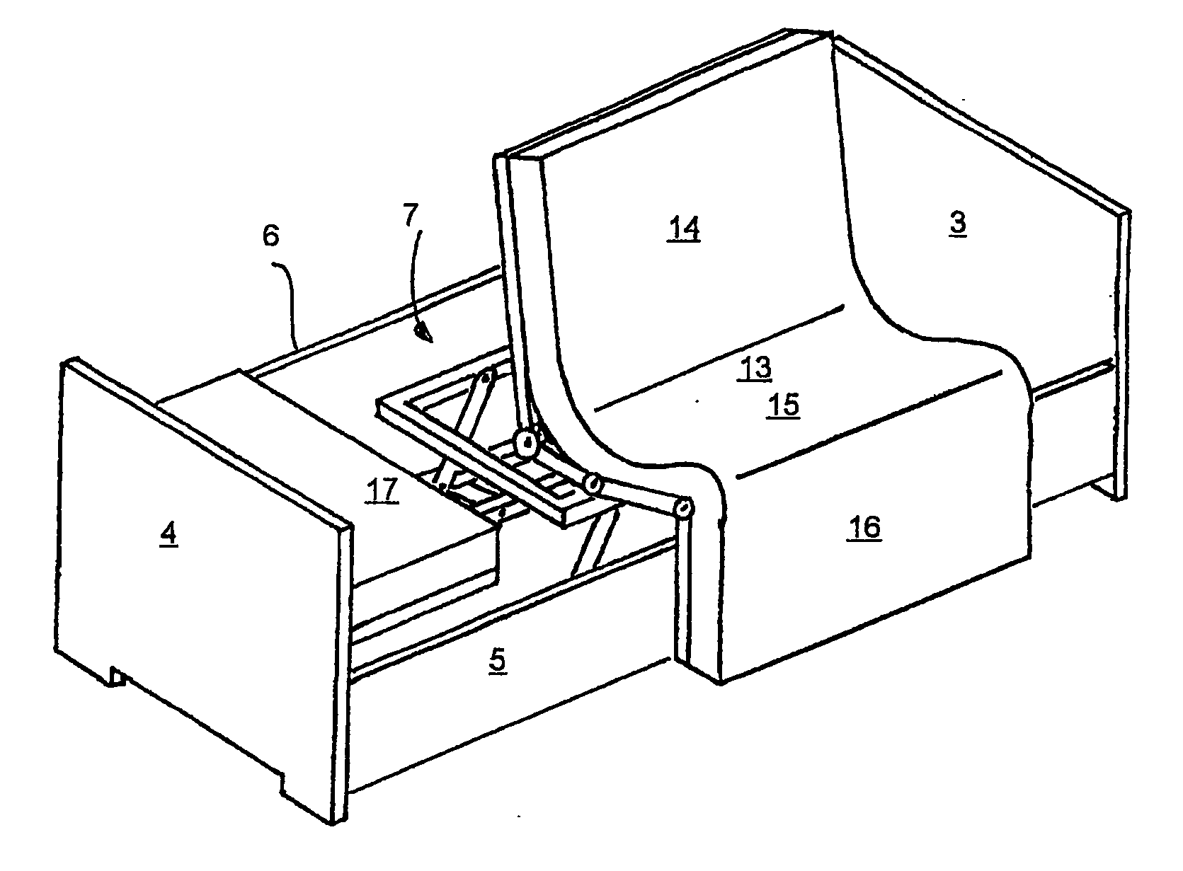
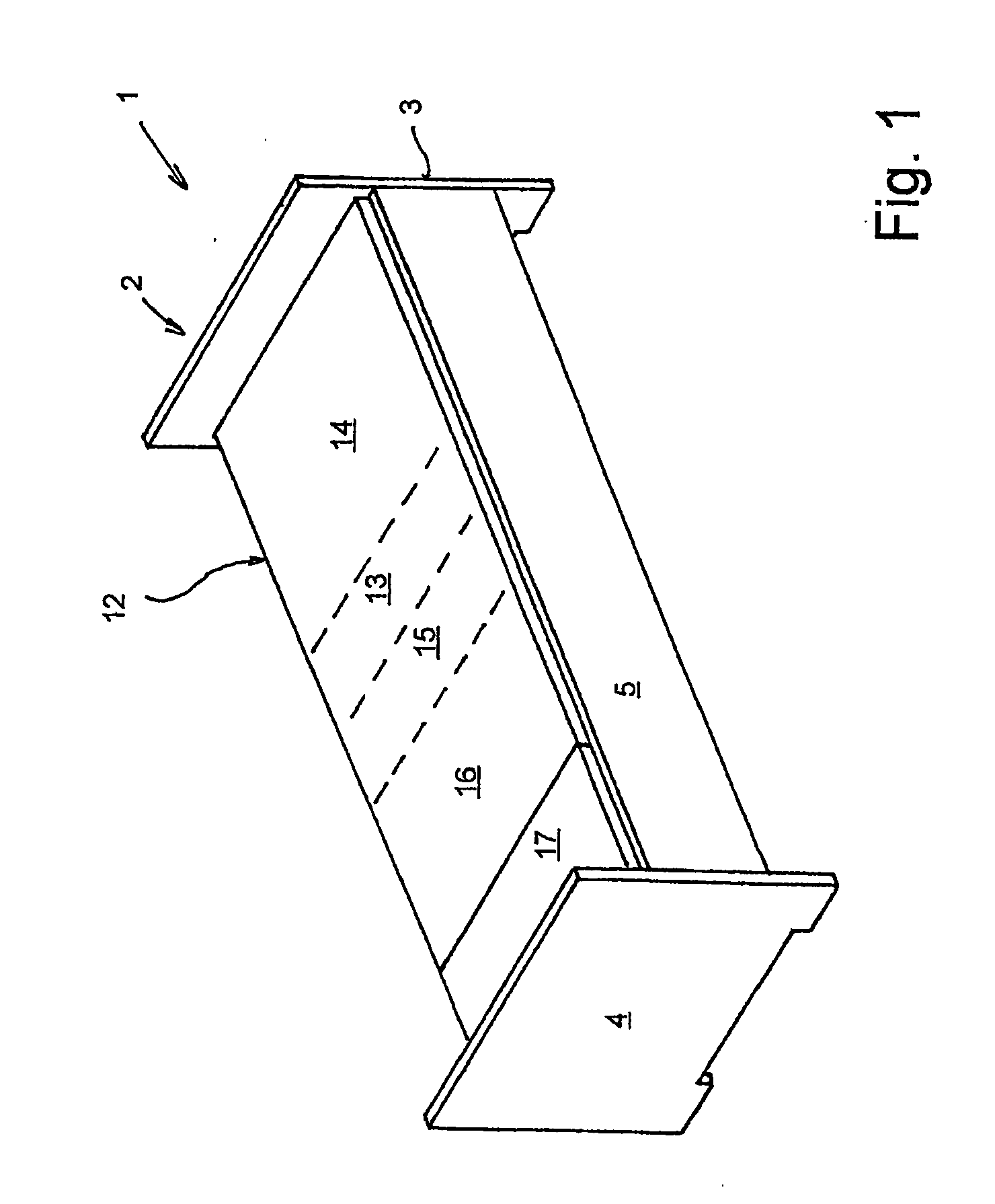
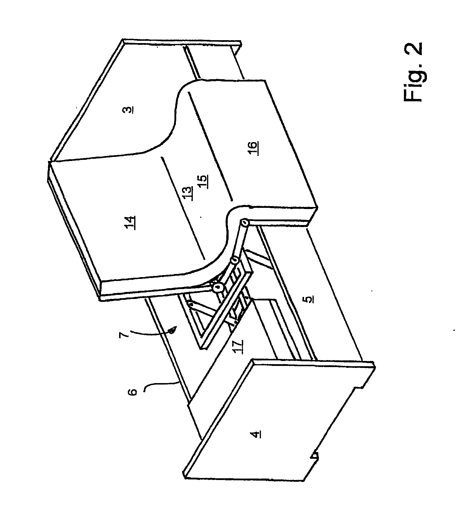
[0021] Referring now more particularly to FIGS. I and 2 of the drawings there is shown an illustrative rotating bed I embodying the present invention. The illustrated rotating bed 1 includes a bed surround 2 with a head part 3, a foot part 4, and front and rear side walls 5, 6, respectively as viewed in FIG. 1. The front side wall 5 is supported a distance from the floor such that a gap is produced between the bottom edge of the side wall 5 and the floor which enables a care provider to place the tips of his feet under the bed. The side wall 5 is supported so that it can move, and in the reclining position of the bed 1 is moved downwardly, as shown in FIG. 2. The moveable support of the side wall 5 is disclosed in detail, for example, in DE 199 12 937 A1, the disclosure of which is incorporated herein by reference.

[0022] Within the bed surround 2 there is a bed frame 7, as seen in FIGS. 2 and 3. The bed frame 7 includes a height-adjustable base 8 having a rotating articulated eleme...


PUM


Abstract

A rotating and sitting-up bed includes a height-adjustable base and a support frame, which is connected to the base by means of a rotating articulated element. The support frame can be rotated by 90 degrees relative to the vertical axis with the help of the rotating articulated element. The support frame is divided into a back section, a center section, a thigh section, and a lower-leg section. In the rotated position, the support frame can fold into a Z shape, wherein the back part projects upwards starting from the center section and the lower-leg part hangs downwards from the thigh part. In addition, a crank mechanism ensures that the thigh part is raised by a few cm at its front edge, which is adjacent to the back of the knee of the patient.

Description

FIELD OF THE INVENTION [0001] The present invention related generally to sleeping beds, and more particularly, to a sleeping bed that can be automatically converted from a normal sleeping position into a chair position. BACKGROUND OF THE INVENTION [0002] From DE 102 00 408 C1, a rotating bed is known which is designed to bring a patient lying in the bed into a sitting position at the edge of the bed. For this purpose, the known bed has a height-adjustable base, which carries a rotating articulated element. A support or mattress frame is connected to the base by means of the rotating articulated element and can be rotated from the normal bed position, in which the longitudinal axis of the mattress frame coincides with the longitudinal axis of the bed, into a cross-wise position. [0003] The support frame is assembled from several sections so that it can be folded Zshaped like a chair or recliner in the cross-wise rotated position. In the chair or recliner shape, the support frame form...

Claims


Application Information

Patent Timeline
IPC IPC(8): A61G7/015A61G7/012A61G7/053A61G7/10A61G7/16
CPCA61G7/012A61G7/015A61G7/053A61G2200/34A61G7/16A61G2200/32A61G7/1076
Inventor BARTHELT, HANS-PETER
Owner BARTHELT HANS PETER
Learn More