Electric double layer capacitor

Inactive Publication Date: 2006-10-26
MITSUBISHI ELECTRIC CORP
View PDF7 Cites 20 Cited by
  • Summary
  • Abstract
  • Description
  • Claims
  • Application Information

AI Technical Summary

Benefits of technology

[0014] An object of the present invention is to provide an electric double layer capacitor which can prevent an increase in the electric resistance of a separator and leaking of an electrolytic solution to the outsi

Problems solved by technology

On the other hand, there is a disadvantage in that the energy density is low in comparison with lithium ion batteries and the like.
In the case where a carbon having a high energy density is used as the material for electrodes, however, the electrodes expand at the time of charging and the electrodes contract at the time of discharging.
In the case where an electrode expands at the time of discharge, the electrolytic solution with which a separator has been impregnated moves toward the electrode side, and the electrolytic solution with which a separator has been impregnated becomes insufficient, creating voids in the pores of a separator.
As a result, a problem arises where the electric resistance of a separator becomes high.
As a result, the electrolytic solution within the exterior case becomes insufficient, making the lifetime shorter, and a problem arises where the overflowed electrolyt

Method used


Image

  • Electric double layer capacitor
  • Electric double layer capacitor
  • Electric double layer capacitor

Examples


first embodiment

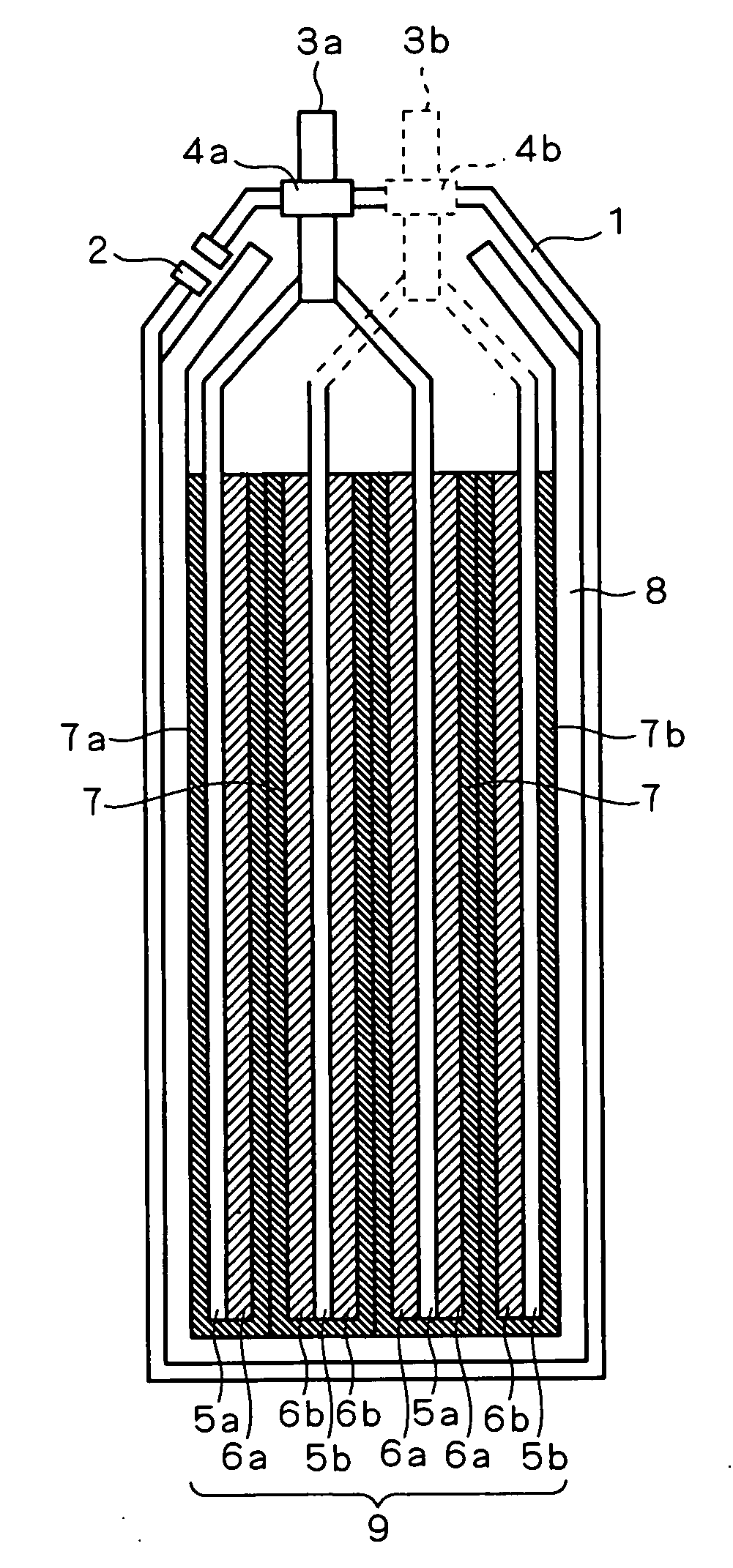
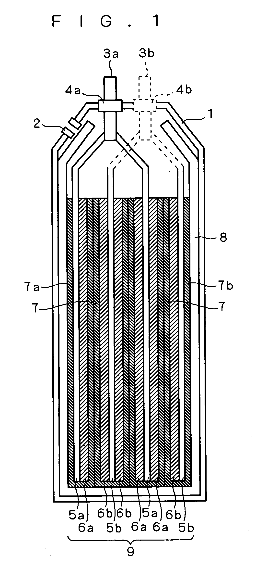
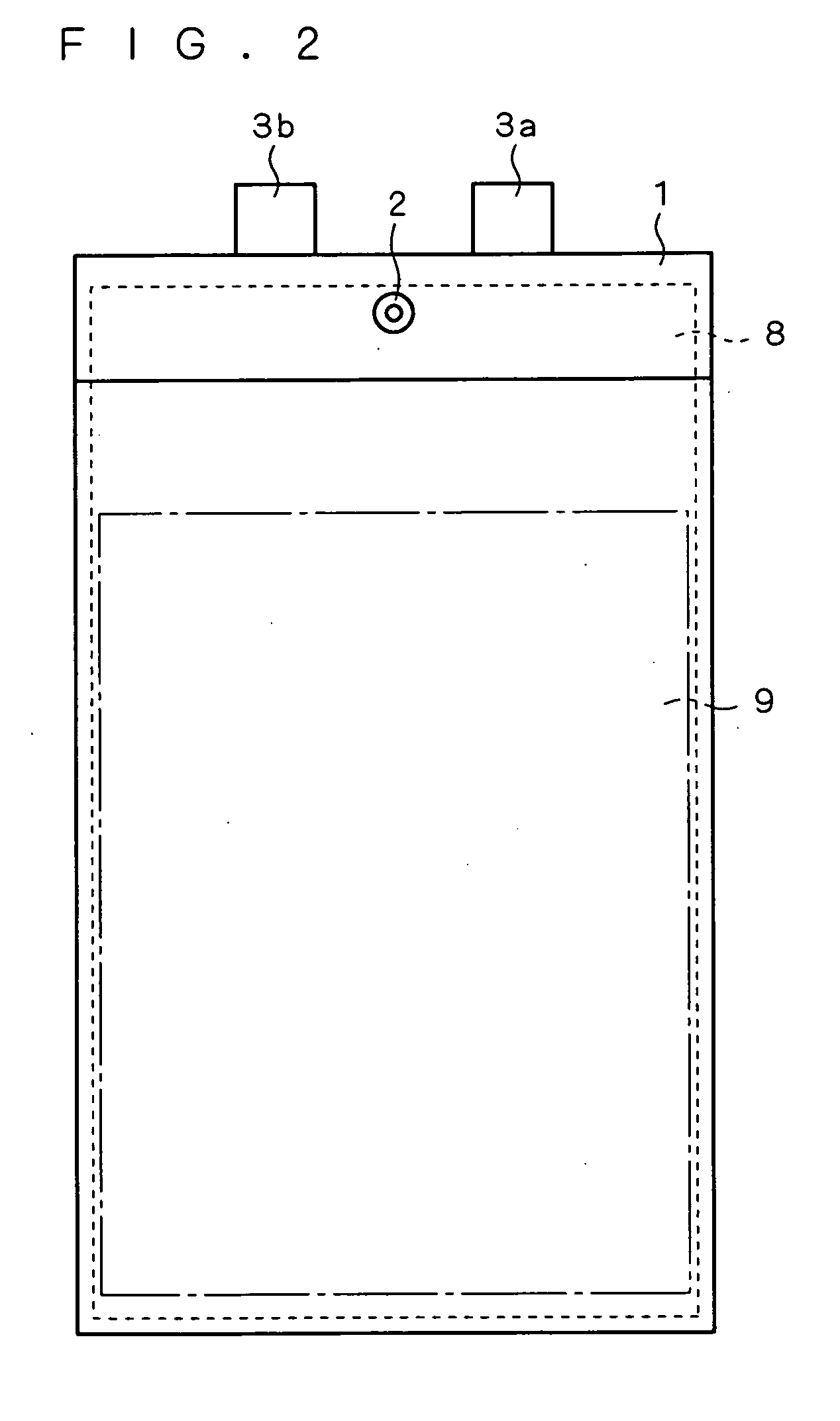
[0060]FIGS. 1 and 2 are respectively a sectional view and a front view showing the structure of an electric double layer capacitor according to a first embodiment of the present invention. With reference to FIGS. 1 and 2, a plurality of pairs of positive electrodes 6a and negative electrodes 6b, which face each other with a porous separator 7 placed in between, are layered on each other, and thereby, a cell portion 9 is formed. As for the positive electrodes 6a and the negative electrodes 6b, layers having a thickness of several hundreds of μm, where activated carbons or Nanogate carbons which each have a size of approximately 10 μm are bounded using a fluorine-based resin such as PTFE (polytetrafluoroethylene) as a binder, are used.

[0061] The positive electrodes 6a are formed on positive electricity collecting plates 5a and the negative electrodes 6b are formed on negative electricity collecting plates 5b. As for the positive electricity collecting plates 5a, aluminum foil is used...

second embodiment

[0078]FIG. 6 is a perspective view showing the structure of an electric double layer capacitor according to a second embodiment of the present invention, and shows the electric double layer capacitor with a portion of the exterior case and the electrolytic solution reservoir 8 cut out. In addition, FIG. 7 is a sectional view schematically showing the structure of a cross section in the case where the electric double layer capacitor shown in FIG. 6 is cut along a virtual plane 20.

[0079] Though an example of a layered type electric double layer capacitor is described in the first embodiment, as shown in FIGS. 6 and 7, the present invention can also be applied to a spiral type electric double layer capacitor.

[0080] In a spiral type electric double layer capacitor, unlike with the layered type, the respective sheets of a positive electrode 6a, a separator 7 and a negative electrode 6b are layered on top of each other and rolled, and thereby, a cell portion 9 is formed. In the electric...

third embodiment

[0082]FIG. 8 is a front view showing the structure of an electric double layer capacitor according to a third embodiment of the present invention. As shown in FIG. 8, the electric double capacitor according to the third embodiment is provided with an exterior case 101, an electrolytic solution reservoir 104 and a cell portion 105 which are contained within this exterior case 101, a positive electrode terminal 102 and a negative electrode terminal 103. The electrolytic solution reservoir 104 is formed of a plurality of electrolytic solution reservoirs 104a.

[0083]FIG. 9 and 10 are a sectional view and a perspective view showing the structure of the electrolytic solution reservoir 104 and the cell portion 105 in a state where the two are contained within the exterior case 101, respectively. FIG. 10 does not show the separator 110 that is shown in FIG. 9, for the sake of convenience. As shown in FIGS. 9 and 10, the cell portion 105 has a structure where a plurality of pairs of a positi...


PUM


Abstract

A porous electrolytic solution reservoir which is capable of being impregnated with an electrolytic solution is provided in an exterior case so as to make contact with a separator. The average diameter of the pores in the electrolytic solution reservoir is greater than the average diameter of pores in the separator. The electrolytic solution reservoir is impregnated with a predetermined amount of electrolytic solution, so that the occupation ratio of electrolytic solution within the pores in the separator becomes 50% or more when fully charged, and the occupation ratio of electrolytic solution within the pores in the electrolytic solution reservoir becomes 100% or less when fully discharged.

Description

BACKGROUND OF THE INVENTION [0001] 1. Field of the Invention [0002] The present invention relates to an electric double layer capacitor. [0003] 2. Description of the Background Art [0004] As disclosed in Japanese Patent Application Laid-Open No. 11-150042 (1999), electric double layer capacitors are provided with polarized electrodes (positive electrode and negative electrode) which face each other with a separator placed in between so that the capacitance of the electric double layers, which are formed on the surface of the polarized electrodes in the electrolytic solution, is used. Electric double layer capacitors are characterized in that an extremely large capacitance can be obtained in comparison with general capacitors such as aluminum capacitors, they have started being used in a wide range of applications such as a back up for electronic equipment, power storage for consumer electronics and copying machines, power supply for the start up from an idle stop of an automobile, a...

Claims


Application Information

Patent Timeline
IPC IPC(8): H01G9/00H01G11/26H01G11/54
CPCH01G9/038H01G9/06H01G9/08H01G11/04H01G11/26H01G11/54Y02E60/13H01G9/155H01G11/52H01G11/82
Inventor MITSUDA, KENROTAKUMA, YOSHIYUKITAKEMURA, DAIGOKUBO, KAZUKIMITANI, TETSUOMIYAMOTO, FUMIYUKIMASUDA, TAKASHI
Owner MITSUBISHI ELECTRIC CORP
Why Eureka
Try Eureka