

Support structure
a support structure and support rod technology, applied in the direction of floating buildings, non-magnetic metal hulls, hull reinforcements, etc., can solve the problems of limiting access to machinery, affecting the operation of the support structure, and affecting the operation of the machine itsel
- Summary
- Abstract
- Description
- Claims
- Application Information
AI Technical Summary
Benefits of technology
Problems solved by technology
Method used
Image

Examples
Embodiment Construction
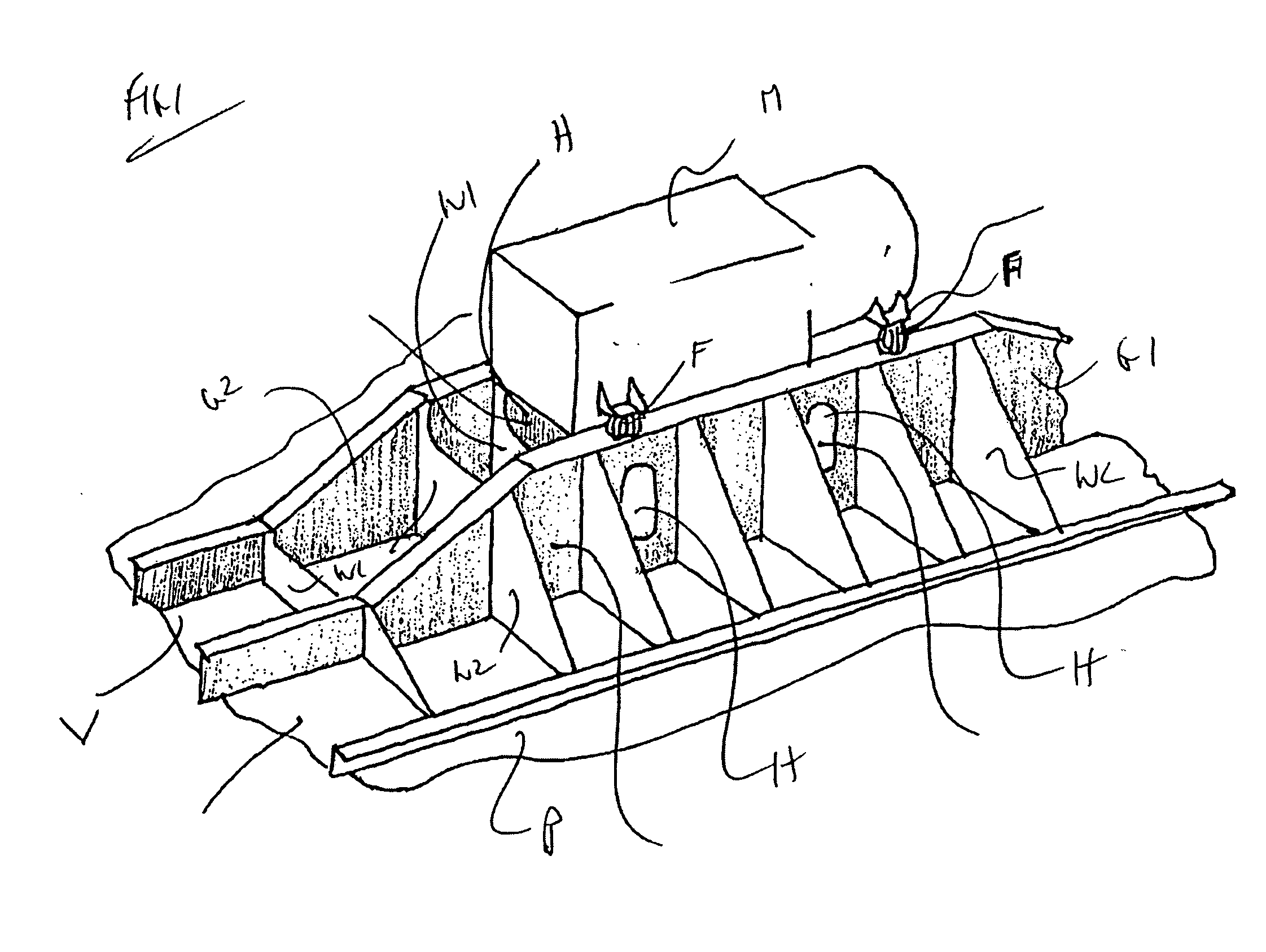
[0017] A conventional installation of auxiliary machinery M is shown in FIG. 1 in which the auxiliary machinery M is supported in an elevated configuration by a pair of spaced girders G1 and G2 via flexible mounts F positioned at each corner of the machinery. The auxiliary machinery M spans the two girders which are welded to project in a parallel array upwardly from the bottom plating P of the vessel V. A series of interconnecting webs W join the girders G1 and G2 and lateral support webs W2 extend from the sides of the girders to the plating P. A series of access holes H are provided along the girders and the webs to provide access to the underside of the auxiliary machinery M. However this is a cumbersome arrangement with very difficult and limited access that has proved unsatisfactory in practice.
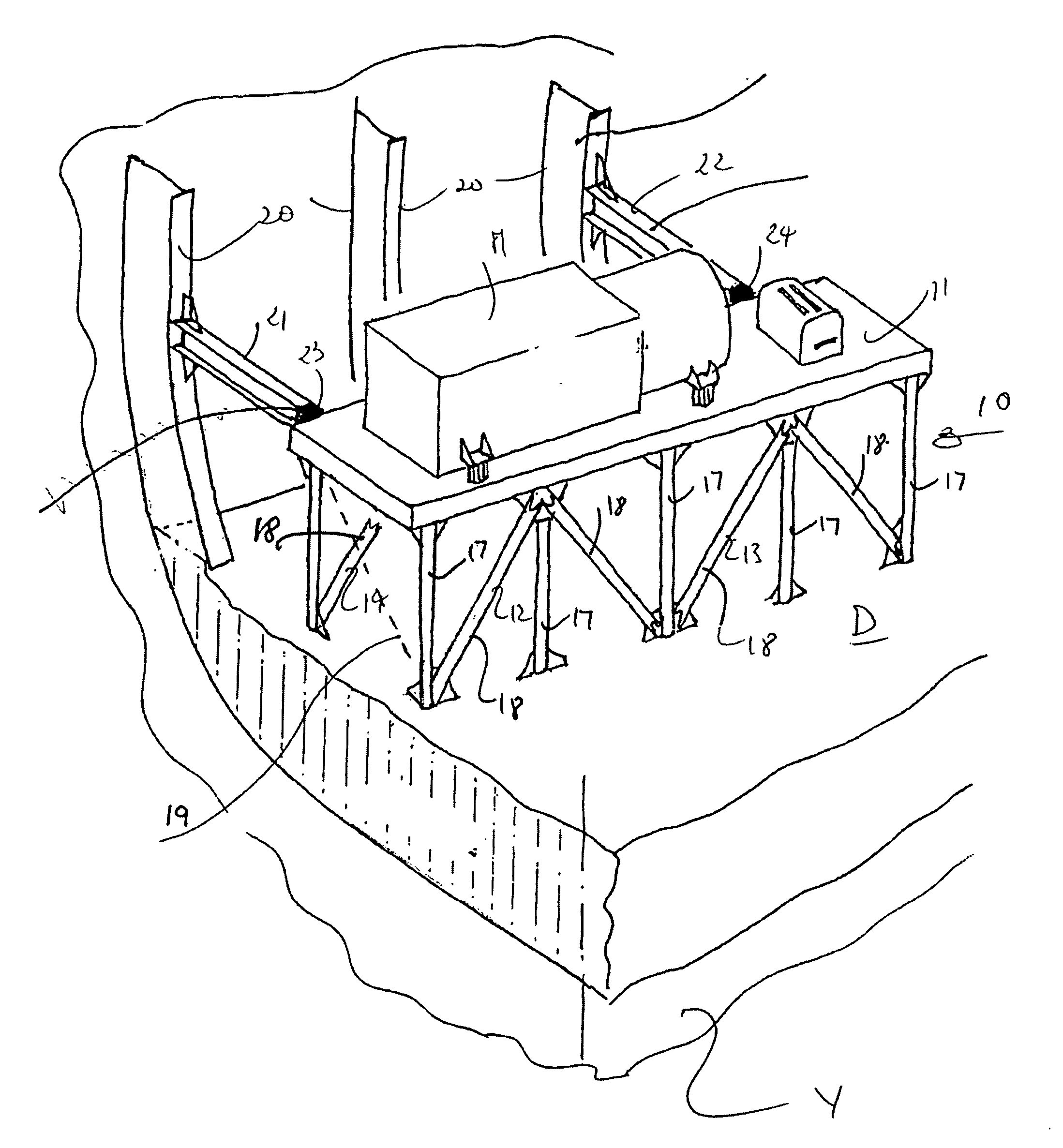
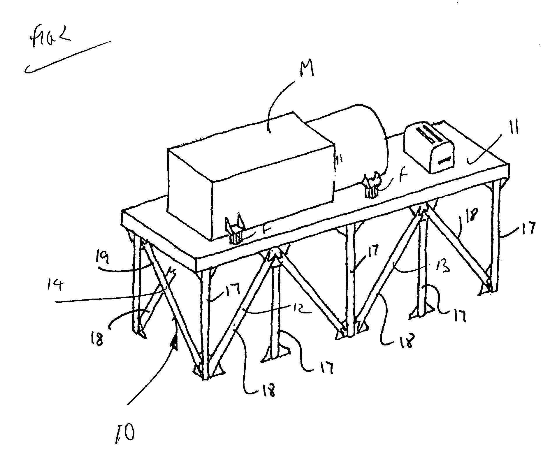
[0018] In the embodiment shown in FIGS. 2 to 5, a trussed frame 10 is used to support a rectangular horizontal plate 11 which in turn supports the auxiliary machinery M via flexible mo...
PUM
 Abstract
Description
Claims
Application Information