Clustered solar-energy conversion array and method therefor

a solar energy and array technology, applied in the direction of thermal-pv hybrid energy generation, light radiation electric generators, lighting and heating apparatus, etc., can solve the problems of marked increase in electrical generation costs, economic and energy inefficiencies, and less economic efficiency of conventional solar-energy generating systems, so as to extract and dissipate heat from sec cells, the effect of reducing dead zones in areas

Inactive Publication Date: 2006-11-02
ARIZONA PUBLIC SERVICE
View PDF18 Cites 51 Cited by
  • Summary
  • Abstract
  • Description
  • Claims
  • Application Information

AI Technical Summary

Benefits of technology

This patented technology relates to improving the efficiency of collecting sunlight on large arrays made up of multiple small parts called modules or subsystems arranged together. These systems use specific arrangements to efficiently direct light towards certain components while also reducing interference between them. By distributing these smaller elements throughout space allows for better performance without adding extra weight or complexity compared to traditional methods like heliostats. Additionally, this design helps prevent thermal degradation caused by high temperatures during operation due to poor air circulations inside the module's enclosure. Overall, this innovative solution provides technical benefits such as improved power generation capabilities, reduced area occupied by devices, increased reliability over longer periods of time, and effective cooling of electronic equipment.

Problems solved by technology

The technical problem addressed in this patent text is the inefficiency and economic inefficiency of conventional solar-energy generating systems that use concentrating photovoltaic cells. These systems suffer from energy inefficiency, heat generation, and tracking issues, which result in increased costs and lower energy and economic efficiency. The text proposes a solution to these problems by utilizing a more efficient form of concentrating photovoltaic systems that capture more solar energy and manage the heat generated by the system effectively.

Method used


Image

  • Clustered solar-energy conversion array and method therefor
  • Clustered solar-energy conversion array and method therefor
  • Clustered solar-energy conversion array and method therefor

Examples


Embodiment Construction

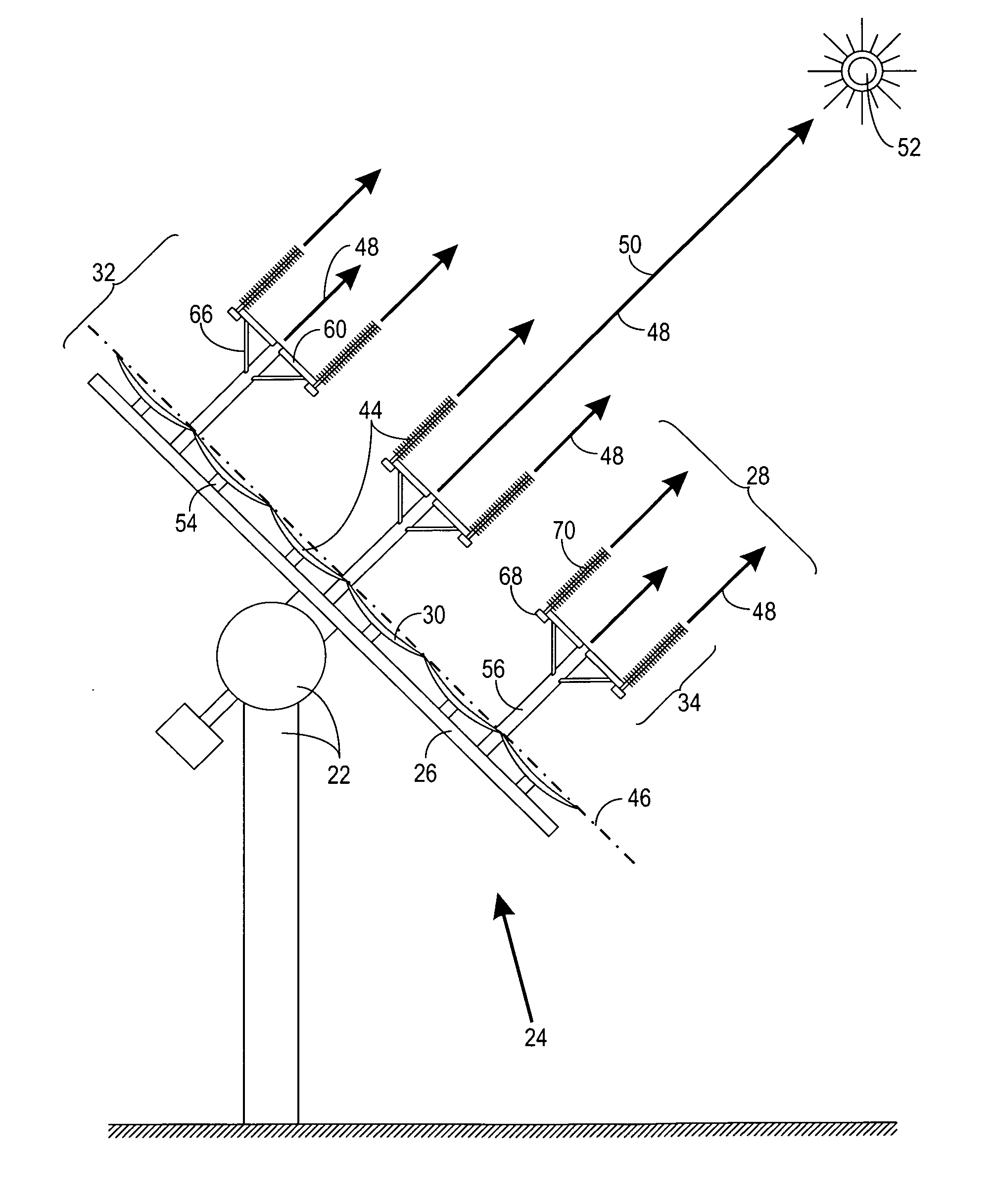
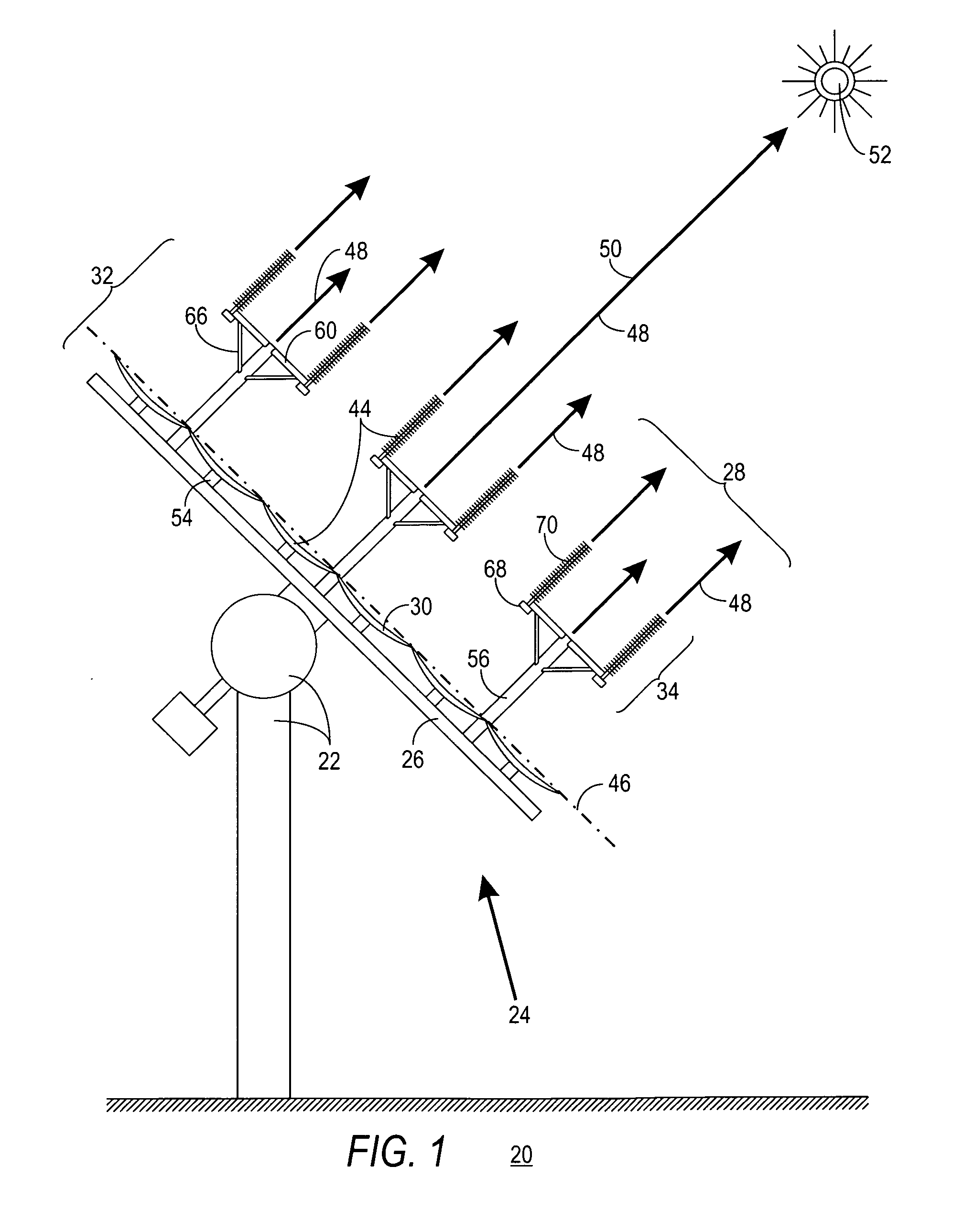
[0037]FIG. 1 shows a side view of a solar-energy conversion (SEC) system 20 in operation in accordance with a preferred embodiment of the present invention. The following discussion refers to FIG. 1.

[0038] Throughout this discussion the emphasis is on the economic efficiency of SEC system 20. While energy efficiency is concerned with the percentage of solar energy converted into electricity under a given set of conditions, economic efficiency is concerned with the number of kilowatts-hours of electricity generated per unit expenditure. Both the amortization of initial structure costs (i.e., component, construction, and installation costs) and the ongoing expenses (spare-parts, maintenance, repair, and operating costs) contribute to the economic efficiency of system 20.

[0039] It is a primary object of the present invention to increase the economic efficiency of system 20 wherever practical. It is recognized that, in many instances, a tradeoff must be made where a decrease in econom...


PUM


Abstract

A solar-energy conversion (SEC) array (24) and method of operation are presented. The array (24) has an aim direction (48) substantially coincident with a solar direction (50) when the array (24) is operational. The array (24) is made up of an array-support structure (26), and a plurality of SEC clusters (28). Each cluster (28) is made up of a number of SEC units (44) and a single cell-support structure (32). Each SEC unit (44) is made up of a concave mirror (30) coupled to the array-support structure (26), and a cell assembly (34). The cell assembly (34) is made up of a cell housing (68) containing an SEC cell (72), and a passive heat-extraction unit (70) thermally coupled to the cell (72) and configured to extract and dissipate heat. The cell-support structure (32) is made up of a support column (56) coupled to the array-support structure (26), and individual support arms (60) coupling each of cell assemblies (34) to the support column (56).

Description


Claims


Application Information

Patent Timeline
Owner ARIZONA PUBLIC SERVICE
Why Eureka
Try Eureka