Vision testing apparatus

a technology for testing apparatus and vision, applied in the field of ophthalmic instruments, can solve the problems of not being sure the child is properly, performing the vision test may not be able to adequately explain the procedure, and children are difficult to understand the concept of rows and columns

Active Publication Date: 2006-11-02
HONEYWELL SAFETY PROD USA INC
View PDF14 Cites 53 Cited by
  • Summary
  • Abstract
  • Description
  • Claims
  • Application Information

AI Technical Summary

Benefits of technology

[0011] In accordance with the present invention, a vision testing apparatus is provided with a lifting mechanism to raise or lower a viewing assembly, the viewing assembly rotatable separately from the lifting mechanism wherein the viewing assembly is operable to obscure at least one character within the viewing assembly to be identified by a patient. The rotatable viewing assembly provides a range of motion independent of the lifting mechanism's position in order to simulate natural line of sight differences between distance and near vision testing. The present invention overcomes the foregoing drawbacks and provides a vision testing apparatus that solves those and other problems.
[0012] Specifically, the vision testing apparatus of the present invention is encased by a number of body panels. A support chassis includes a base and sidewalls. The lifting mechanism includes arms connecting the sidewalls to the viewing assembly. The viewing assembly is at least partially enclosed by a viewing housing. The arms rotate through a range of motion between a first storage / transportation configuration and a range of raised configurations (the apparatus operates in any configuration). In a storage configuration, the viewer housing is lowered towards the base to form a compact package. The raised configurations involve raising the viewer housing away from the base along a nearly vertical vector. A height adjustable viewing assembly in accordance with the present invention is effective for patients of differing heights.
[0016] To accommodate patients with corrective eyewear and / or to provide a more natural line of sight, the patient or tester can operate a mechanism located on the viewing assembly that adjusts the angle of the viewing assembly relative to the patient. In one preferred embodiment, this line of sight adjustment mechanism is a rack-and-pinion mechanism. This rack-and-pinion mechanism allows the viewing assembly to be rotated in relation to the chassis so that the patient's viewing angle can be manipulated. This is of particular importance to patients with bifocal, trifocal or progressive lens, but the ability to adjust the viewing angle generally enables a vision test to be administered using a natural line of sight (i.e., downward viewing angle for near vision testing and a straight-ahead viewing angle for far vision testing). The natural line of sight is achieved while the apparatus uses only a single optical path.
[0018] In a preferred embodiment of the transparent panel, the panel includes a number of pixels that can be individually activated. In an activated state, the individual pixels are operable to shade or block light passing through that portion of the panel. In an unactivated state, light passes through the panel at that pixel without any shading noticeable to the patient. This embodiment of the present invention, therefore, allows a tester to selectively activate pixels so that individual characters on a test slide are highlighted or isolated via a tester-operated control board, remote control, or the like. The panel can be operated so as to allow only one object, a row of objects, or a column of objects to be unobscured or visible to the patient. Characters to be ignored appear to be shaded or are not visible to the patient. The character or characters to be viewed by the patient would effectively be highlighted. It is also possible to deactivate each pixel so that all the objects or characters are equally visible.

Problems solved by technology

While it is often necessary to test small children for vision problems, it is very difficult for children to understand the concept of rows and columns.
The party performing the vision test may not be able to adequately explain the procedure or may not be sure the child is properly reading the column or row the tester is indicating.
Even where particular rows or columns are highlighted, the patient must understand concepts such as “left to right” or “top to bottom.” This can be difficult to convey to children, mentally handicapped patients, patients that are not fluent in the tester's language, or in other similar circumstances.
This leads to bulky and overly complicated vision testing machines.
Vision testing devices with only one optical path do not account for patients who have these types of lenses, which is to say that patients look straight into a vision testing device when testing “near” vision.
This unnatural line of sight can lead to inaccurate results.
Patients with corrective lenses are also inconvenienced by the need to adjust their lenses or head position to account for the unnatural line of sight.
Even with multiple optical paths, the arbitrary angle supplied by the vision testing apparatus may not be optimum for a given patient.
Moreover, it may be difficult for a patient to find the ideal angle and / or to hold their head or eyewear at that angle.
For instance, aged patients may be unable to steadily hold their eyewear at the angle necessary to test the near vision portion of their corrective lenses.
Yet, many vision testing machines cannot be collapsed or otherwise condensed and they, therefore, require bulky, hard storage or transport cases.

Method used


Image

  • Vision testing apparatus
  • Vision testing apparatus
  • Vision testing apparatus

Examples


Embodiment Construction

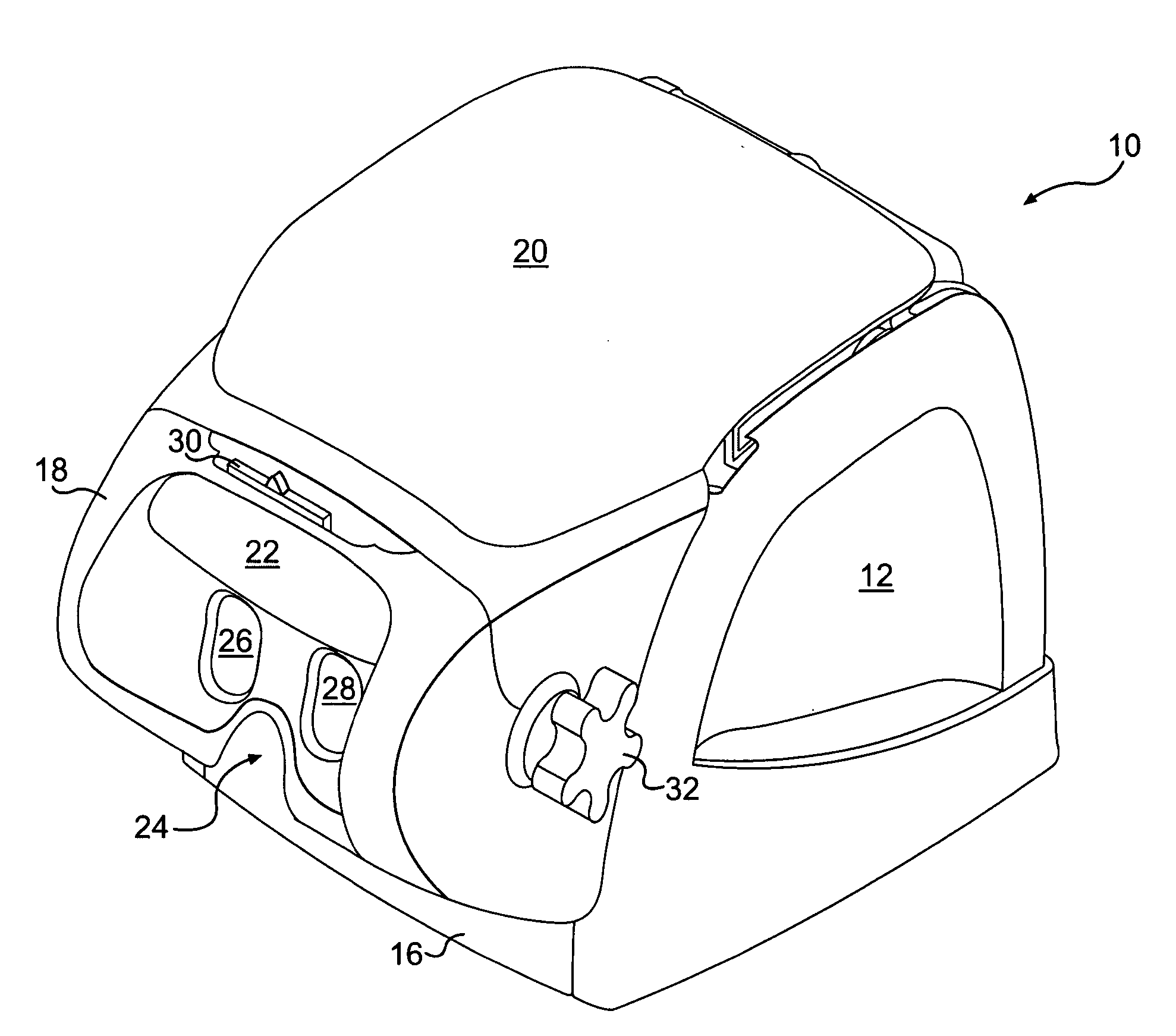
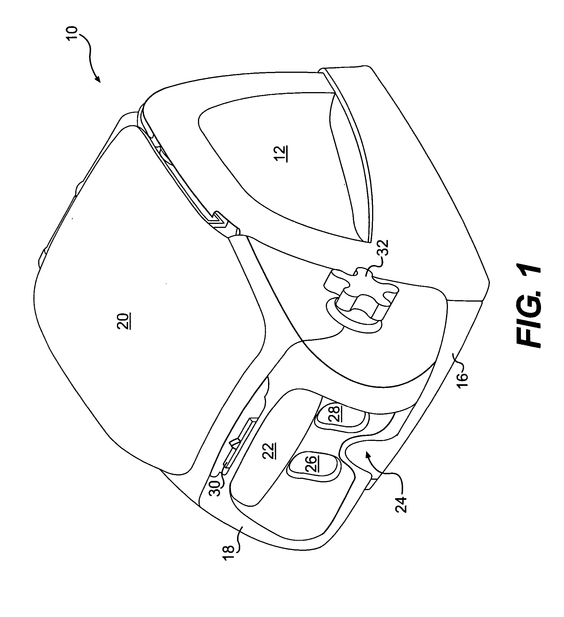
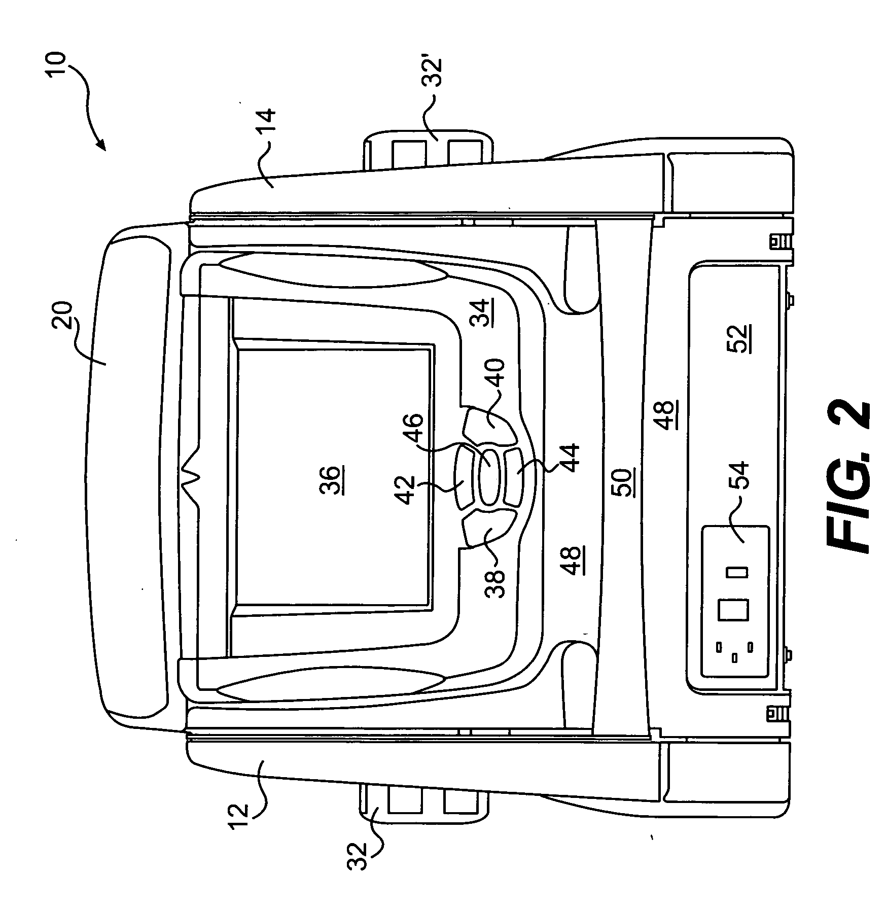
[0033] The invention will be described in the context of one or more preferred embodiments. FIGS. 1-13 illustrate a vision testing apparatus in accordance with preferred embodiments of the present invention, but it is to be understood that an engineer or designer having ordinary skill in the art of vision testing apparatus assembly will be able to create a vision testing apparatus that incorporates the teachings of the present invention but which may look different and incorporate different, alternative parts without leaving the scope of the invention.

[0034] Turning now to FIGS. 1 and 2, there is illustrated a vision testing apparatus 10 that is encased by various body panels including a right side cover 12 and a corresponding left side cover 14. A front trim piece 16, a lens cover 18, and a top cover 20 provide an aesthetic quality. Lens cover 18 and top cover 20 are part of a viewer housing 21 described below.

[0035] In use, a patient rests their forehead against a headrest 22 wi...


PUM


Abstract

A vision test apparatus includes a viewing assembly connected to a chassis wherein the viewing assembly creates an optical path between an image display and at least one front lens. A near / far assembly includes a secondary lens selectively operable with the front lens to create virtual visual distances. An optional transparent panel intersects the optical path and operates at least partially obscure the image display so that the vision testing apparatus has a means to isolate a portion of the image display. A lifting mechanism is operable to raise or lower the viewing assembly for patients of various heights. The viewing apparatus is also rotatable independently of said chassis to present natural lines of sight to a patient during near and far testing.

Description

FIELD OF THE INVENTION [0001] The present invention relates to the field of ophthalmic instruments, and more particularly, to an improved vision tester designed for accurate and precise measurement of visual performance BACKGROUND OF THE INVENTION [0002] Many types of vision testers are known including those previously described by the present applicant in U.S. Pat. Nos. 6,350,032 and 4,740,072. These disclosures are incorporated by reference herein. [0003] Technology related to healthcare devices and procedures is continuously improving. This constant improvement makes it possible to identify new populations that are underserved by existing technologies and to also assist these newly identified populations. Advances in technology lead to the improvement and modification of existing devices so that new and old healthcare issues can be addressed in more efficient and effective ways. [0004] Vision testing is one healthcare area that benefits greatly from improved technology. Current v...

Claims


Application Information

Patent Timeline
Patent Type & Authority Applications(United States)
IPC IPC(8): A61B3/00
CPCA61B3/032A61B3/028A61B3/02
Inventor CLEMONS, MICHAELREMEDIOS, PHILIP
Owner HONEYWELL SAFETY PROD USA INC
Why Eureka
Try Eureka