Retinal prosthesis and method of manufacturing a retinal prosthesis

a retinal prosthesis and retinal technology, applied in the field of retinal prosthesis and manufacturing method, can solve the problems of large prosthetic device size, bulky, and insufficient simulated vision to truly aid the visually impaired, and achieve the effect of reducing the number of retinal prosthesis parts

Active Publication Date: 2006-11-02
CORTIGENT INC
View PDF27 Cites 43 Cited by
  • Summary
  • Abstract
  • Description
  • Claims
  • Application Information

AI Technical Summary

Benefits of technology

[0016] The present invention is an improved hermetic package for implantation in the human body. The implantable device of the present invention includes an electrically non-conductive substrate including electrically conductive vias through the substrate. A circuit is flip-chip bonded to a subset of the vias. A second circuit is wire bonded to another subset of the vias. Finally, a cover is bonded to the substrate such that the cover, substrate and vias form a hermetic package.

Problems solved by technology

While some of these early attempts met with some limited success, these early prosthetic devices were large, bulky and could not produce adequate simulated vision to truly aid the visually impaired.

Method used


Image

  • Retinal prosthesis and method of manufacturing a retinal prosthesis
  • Retinal prosthesis and method of manufacturing a retinal prosthesis
  • Retinal prosthesis and method of manufacturing a retinal prosthesis

Examples


Embodiment Construction

[0026] The following description is of the best mode presently contemplated for carrying out the invention. This description is not to be taken in a limiting sense, but is made merely for the purpose of describing the general principles of the invention. The scope of the invention should be determined with reference to the claims.

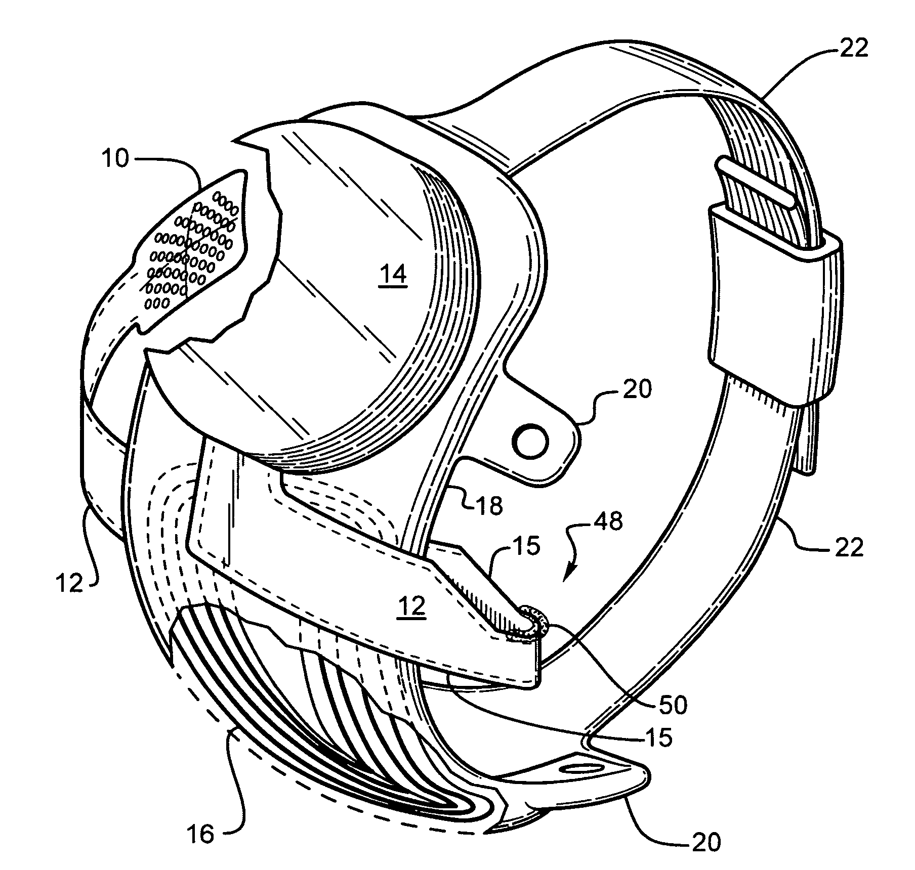
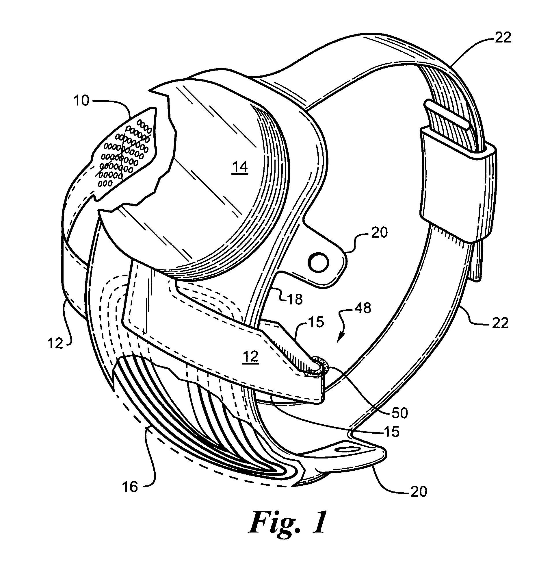
[0027] The present invention is an improved hermetic package for implanting electronics within a body. Electronics are commonly implanted in the body for neural stimulation and other purposes. The improved package allows for miniaturization of the package which is particularly useful in a retinal or other visual prosthesis for electrical stimulation of the retina.

[0028]FIG. 1 shows a perspective view of the implanted portion of the preferred retinal prosthesis. A flexible circuit 1 includes a flexible circuit electrode array 10 which is mounted by a retinal tack (not shown) or similar means to the epiretinal surface. The flexible circuit electrode array 1...


PUM


Abstract

The present invention is an improved package and configuration for an implantable retinal prosthesis. The retinal prosthesis of the present invention includes an electrode array suitable to be mounted in close proximity to a retina, an electronics package and inductive receiving coil mounted next to each other on a strap surrounding the sclera so that the height above the sclera of the prosthesis is minimized.

Description

CROSS-REFERENCE TO RELATED APPLICATIONS [0001] This application claims benefit of U.S. Provisional Patent application Ser. No. 60 / 675,980, filed on Apr. 28, 2005, entitled “Implantable Chip Scale Package and Low Profile Ocular Mount,” the disclosure of which is incorporated herein by reference. [0002] This application is related to, but not dependent on, U.S. patent application Ser. Nos. 09 / 823,464 for Method and Apparatus for Providing Hermetic Feedthroughs filed Mar. 30, 2001; Ser. No. 10 / 174,349 for Biocompatible Bonding Method and Electronics Package Suitable for Implantation filed Jun. 17, 2002; Ser. No. 10 / 236,396 for Biocompatible Bonding Method and Electronics Package Suitable for Implantation filed Sep. 6, 2002; Ser. No. 10 / 820,240 for Retinal Prosthesis with Side Mounted Inductive Coil filed Apr. 6, 2004; Ser. No. 11 / 206,482 for Package for an Implantable Medical Device filed Aug. 17, 2005 and Ser. No. 11 / 207,644 for Flexible Circuit Electrode Array filed Aug. 19, 2005 all...

Claims


Application Information

Patent Timeline
Patent Type & Authority Applications(United States)
IPC IPC(8): A61N1/18
CPCA61N1/0543A61N1/375A61N1/36046A61N1/37518H01L2224/16227H01L2224/32225H01L2224/73253H01L2924/15311H01L2924/16251H01L2924/19104H01L2924/19107A61N1/3758A61N1/3787
Inventor GREENBERG, ROBERT JAYOK, JERRYTALBOT, NEIL HAMILTONWILKIN, KEVIN
Owner CORTIGENT INC
Why Eureka
Try Eureka