Percutaneous Heart Valve Prosthesis

a technology of mitral valve and prosthesis, applied in the field of percutaneous mitral valve prosthesis, can solve the problems of causing death, affecting the function affecting the quality of life of mitral valve prosthesis,

Active Publication Date: 2008-10-02
PERCUTANEOUS CARDIOVASCULAR SOLUTIONS
View PDF22 Cites 725 Cited by
  • Summary
  • Abstract
  • Description
  • Claims
  • Application Information

AI Technical Summary

Benefits of technology

[0064]a flexible skirt extending about a periphery of said valve body for blocking bloodflow in said one direction between said valve body and the native wall of a valve orifice in use.

Problems solved by technology

Heart valve regurgitation is a condition whereby the heart valve does not seal completely as a result of disease or injury, and may have fatal consequences.
Whilst there has been some success in developing replacement aortic valve prostheses for delivery via percutaneous catheter-based methods, these techniques have not been particularly successful when applied to mitral valve prostheses.
Mitral valve replacement is firstly made difficult as a result of the anatomy of the mitral valve, and particularly that of the mitral valve annulus in which the mitral valve is leaflets are located.
The mitral valve annulus is typically very distorted, and of unpredictable and non-uniform geometries, as compared to the relatively uniform aortic valve annulus.
This unpredictable anatomy makes it difficult to design a pre-constructed mitral valve prosthesis that would fit the mitral valve annulus in a satisfactory manner for safe, stable and meticulous deployment.
As a result, the mitral valve annulus cannot be subjected to any significant radial forces, as would be typical with an expanding stent type of valve prosthesis, as such radial forces would tend to collapse the aortic outflow tract, resulting in circulatory collapse with likely fatal consequences.
As a result of these difficulties, firm anchoring of a deployed mitral valve prosthesis is currently not readily obtainable.
This is a technically extremely challenging task associated with the potentially fatal complication of profound mitral regurgitation that may not be adequately addressed by the subsequent valve replacement.
The lack of an effective mitral valve may lead to overwhelming hemodynamic instability that may not be tolerated by the already compromised left ventricle and overwhelming pulmonary edema may rapidly result.

Method used


Image

  • Percutaneous Heart Valve Prosthesis
  • Percutaneous Heart Valve Prosthesis
  • Percutaneous Heart Valve Prosthesis

Examples


Embodiment Construction

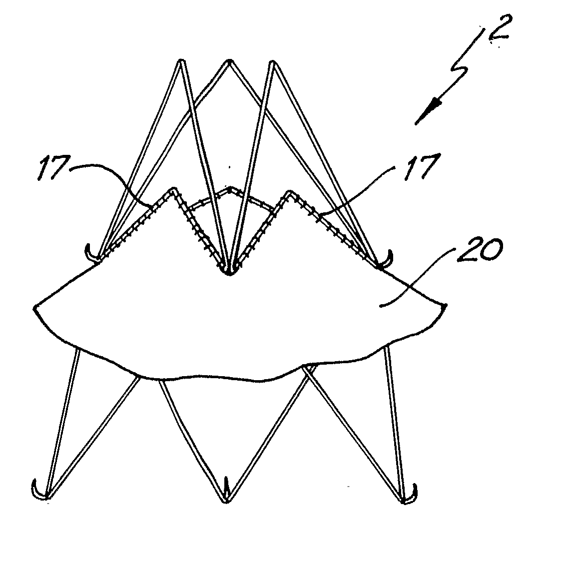
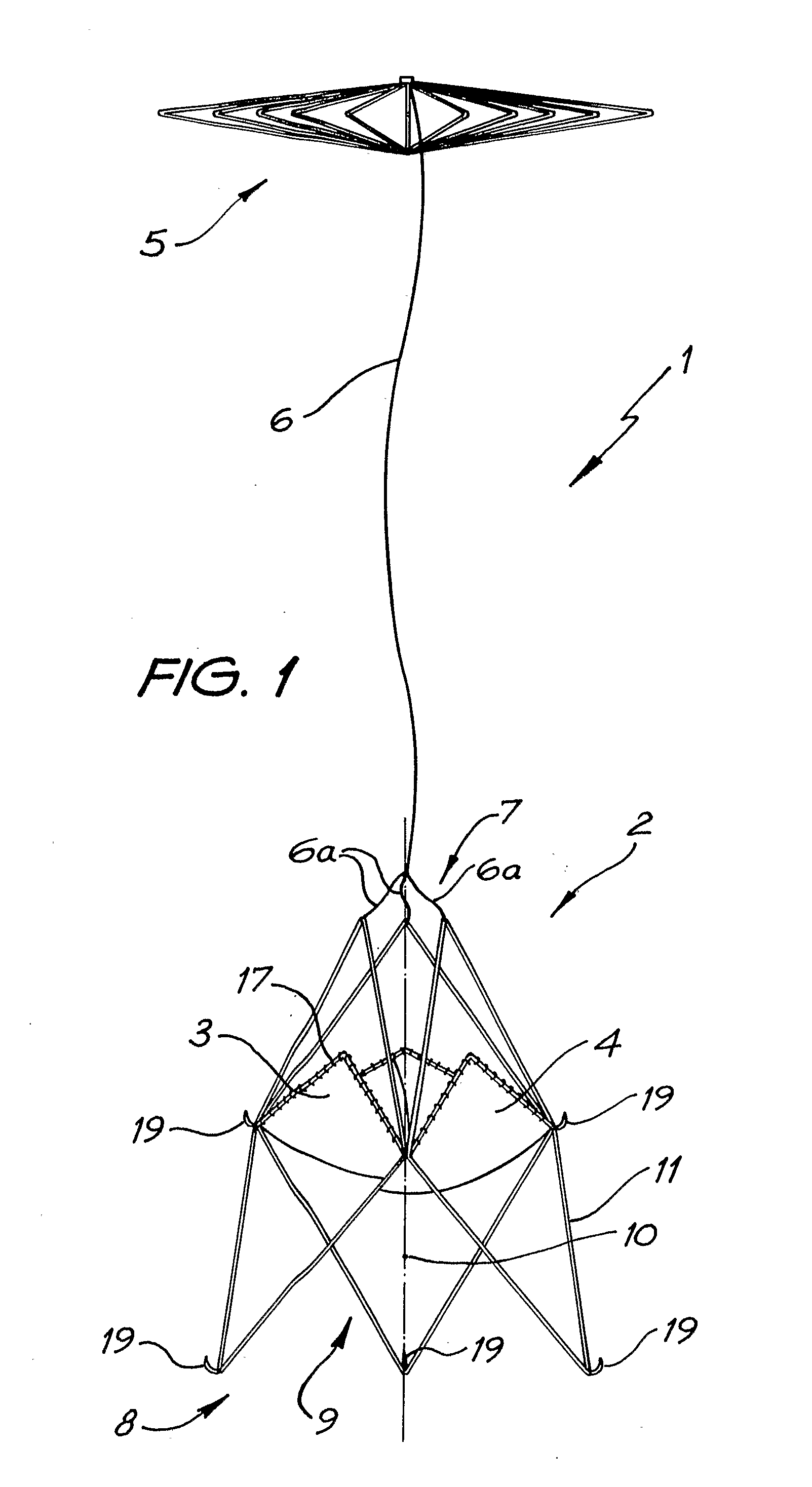
[0101]Referring specifically to FIG. 1, a percutaneous heart valve prosthesis, in the form of a mitral valve prosthesis 1, comprises a valve body 2, first and second flexible valve elements 3, 4, an anchor device 5 and an anchor line 6 secured to and extending between the valve body 2 and the anchor device 5.

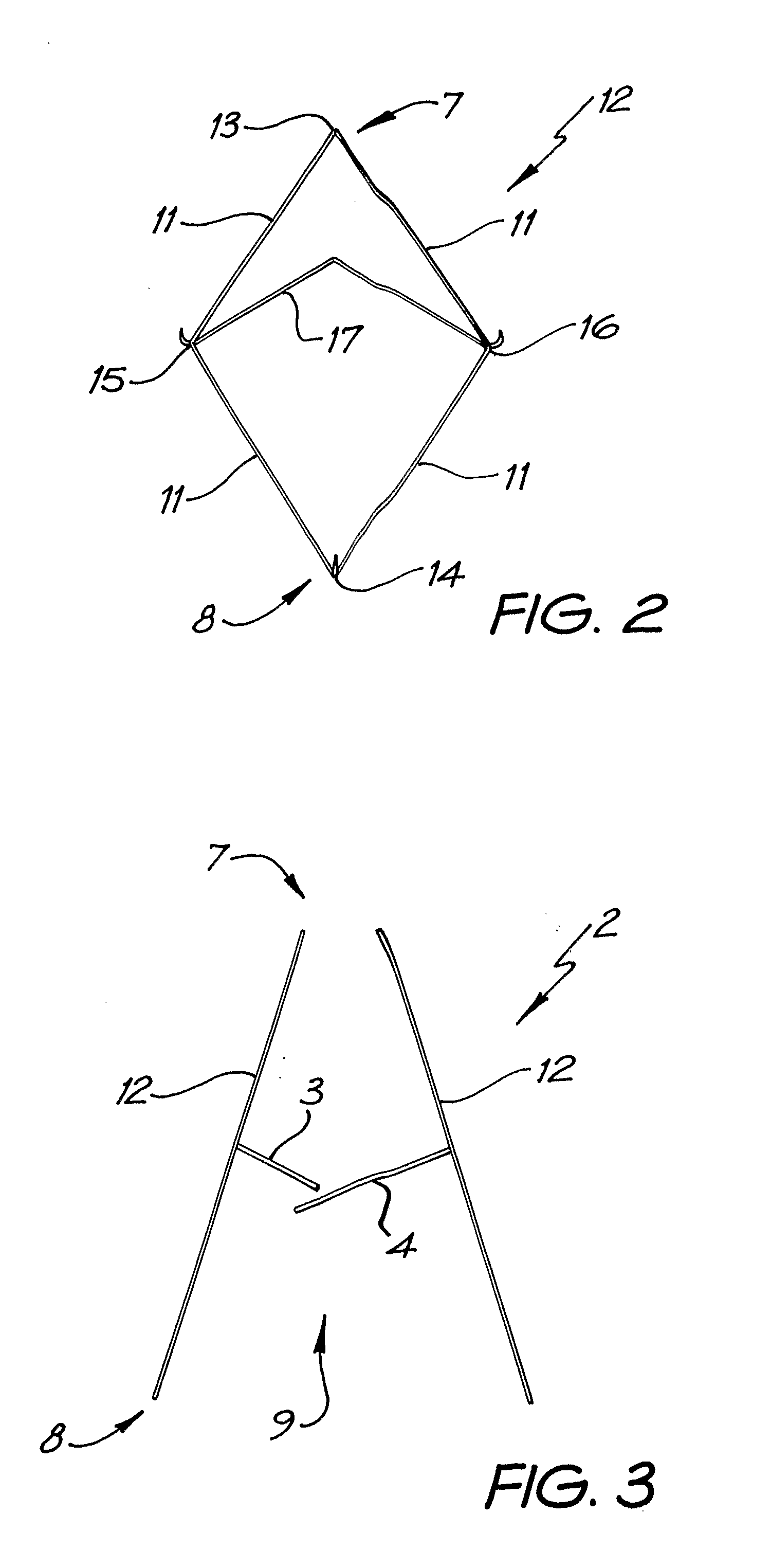
[0102]The valve body 2 has a first end 7 and a second end 8. A blood flow passage 9 extends along a longitudinal axis 10 between the valve body first end 7 and the valve body second end 8. The valve body 2 is configured so as to be collapsible about the longitudinal axis 10 to enable the valve body 2 to be located in a catheter for delivery of the prosthesis 1, as will be discussed further below.

[0103]The valve 2 is in the form of a collapsible valve body frame formed of elongate elastic valve body frame elements 11. Each of the valve body frame elements 11 may be suitably formed as wires of a superelastic shape memory material. A particularly suitable material is nitinol, a nic...


PUM


Abstract

A percutaneous heart valve prosthesis (1) has a valve body (2) with a passage (9) extending between the first and second ends (7, 8) of the valve body (2). The valve body (2) is collapsible about a longitudinal axis (10) of the passage (9) for delivery of the valve body (2) via a catheter (18). One or more flexible valve leaflets (3, 4) are secured to the valve body (2) and extend across the passage (9) for blocking bloodflow in one direction through the passage (9). An anchor device (5), which is also collapsible for delivery via catheter (18), is secured to the valve body (2) by way of an anchor line (6). A failed or failing mitral heart valve (101) is treated by percutaneously locating the valve body (2) in the mitral valve orifice (102) with the anchor device (5) located in the right atrium (107) and engaging the inter-atrial septum (103), such that the taught anchor line (6) acts to secure the valve body (2) within the mitral valve orifice (102).

Description

FIELD OF THE INVENTION[0001]The present invention relates to a percutaneous heart valve prosthesis, and particularly relates to, but is not limited to, a percutaneous mitral valve prosthesis.BACKGROUND OF THE INVENTION[0002]Heart valve regurgitation is a condition whereby the heart valve does not seal completely as a result of disease or injury, and may have fatal consequences.[0003]Malfunctioning heart valves have typically been replaced with mechanical or biologic heart valve prostheses using highly invasive open-heart surgery techniques. Whilst there has been some success in developing replacement aortic valve prostheses for delivery via percutaneous catheter-based methods, these techniques have not been particularly successful when applied to mitral valve prostheses.[0004]Mitral valve replacement is firstly made difficult as a result of the anatomy of the mitral valve, and particularly that of the mitral valve annulus in which the mitral valve is leaflets are located. The mitral...

Claims


Application Information

Patent Timeline
Patent Type & Authority Applications(United States)
IPC IPC(8): A61F2/24
CPCA61F2/2418A61F2/2436A61F2002/8486A61F2220/0075A61F2230/0067A61F2220/0058A61F2230/005A61F2230/0054A61F2220/0016A61F2/2487A61F2/24A61F2/2412A61F2/2409A61F2/2427
Inventor THAMBAR, SUKUJAYASINGHE, STAYAJIT ROHAN
Owner PERCUTANEOUS CARDIOVASCULAR SOLUTIONS
Why Eureka
Try Eureka