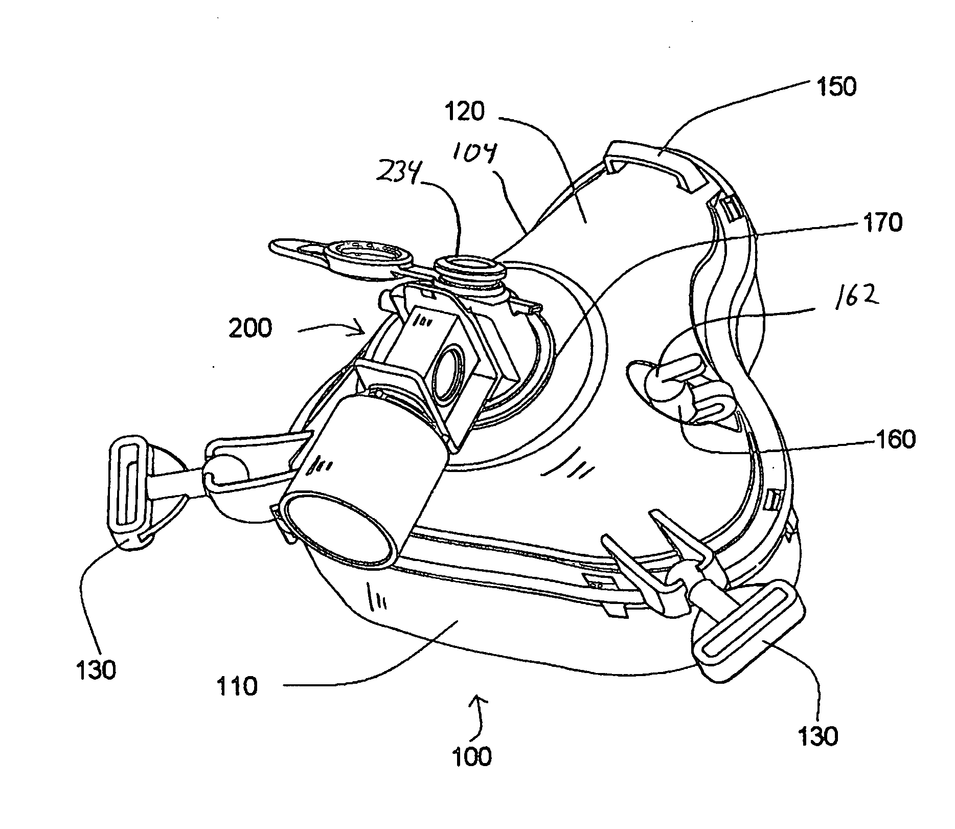
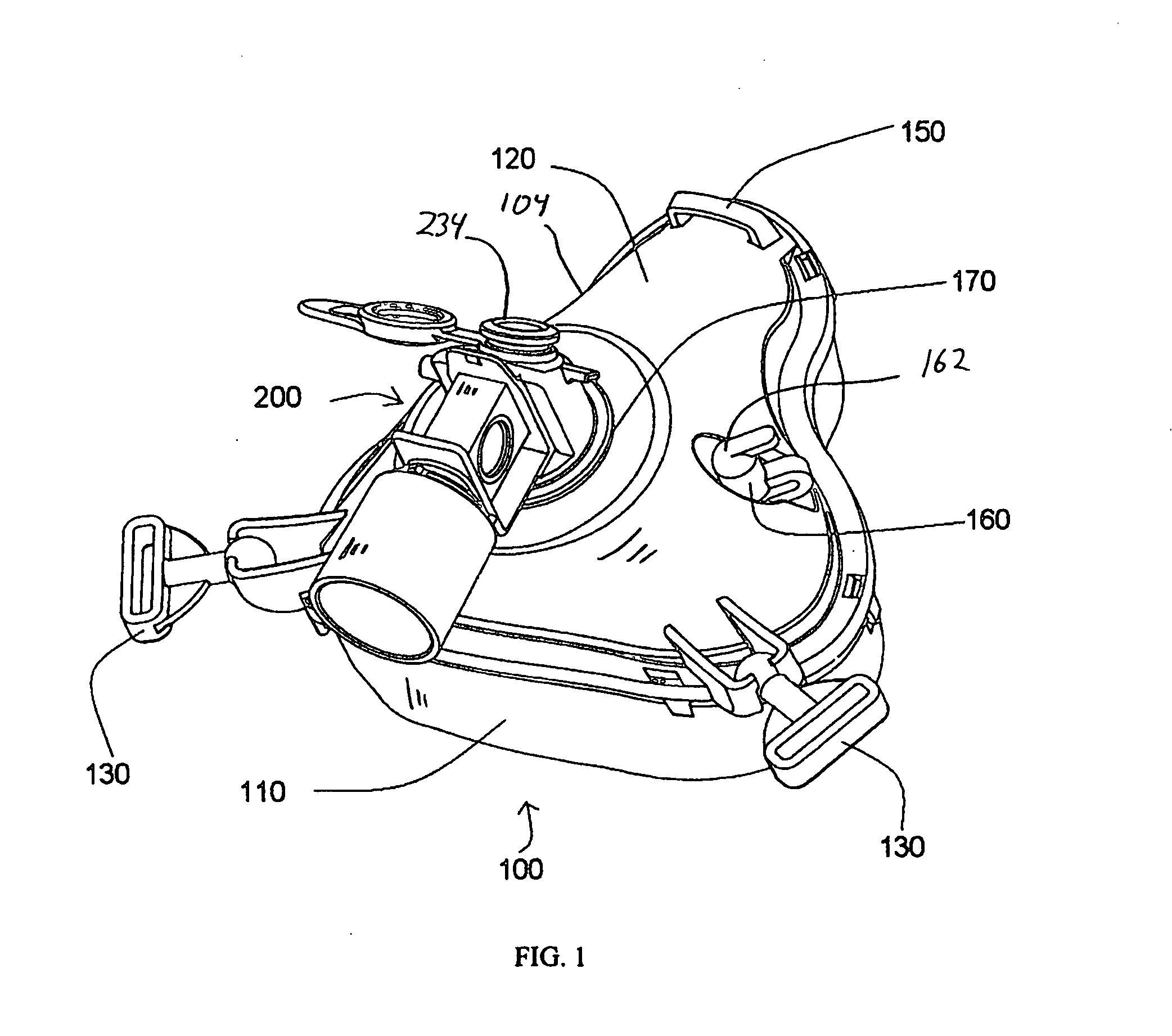
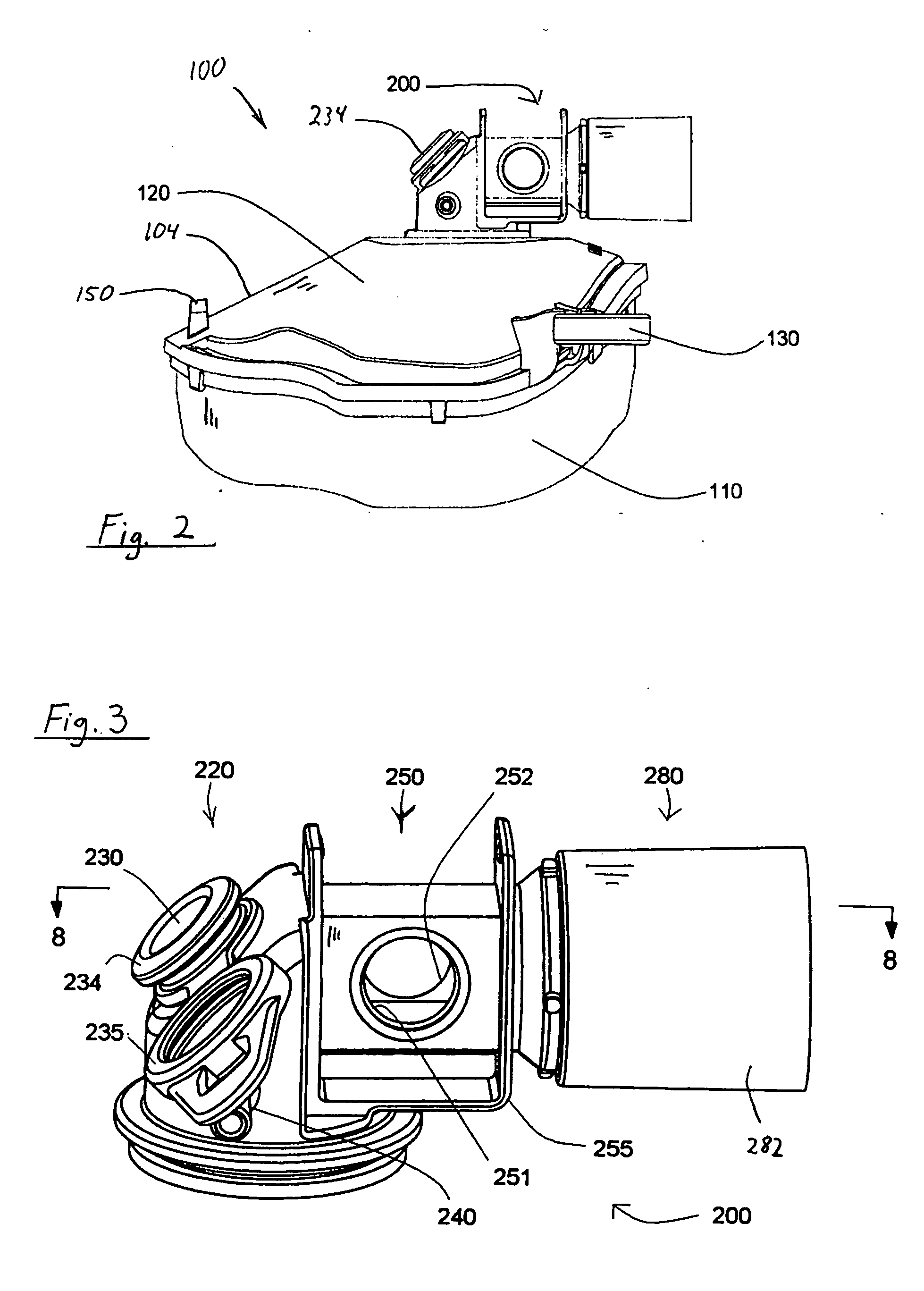
Patient interface with respiratory gas measurement component
a gas measurement and patient interface technology, applied in the field of masks with respiratory gas measurement sites, can solve the problems of complicated interpretation of measurement, added inconvenience, and limited use in clinical practice of masks, and achieve the effect of improving the accuracy of the measurement, simplifying the interpretation of measurement, and increasing the complexity of the gas measuring apparatus
- Summary
- Abstract
- Description
- Claims
- Application Information
AI Technical Summary
Benefits of technology
Problems solved by technology
Method used
Image
Examples
second embodiment
[0056]FIGS. 11-12 illustrate a patient interface assembly 300 including a mask attachment 201 according to the principles of the present invention and shown positioned on a user's face. A headgear 140 secures the patient interface assembly on the user. The present invention contemplates that the headgear can be any conventional headgear suitable for this purpose. Thus, the details of the headgear are omitted from the present description for the sake of brevity
[0057] As shown in FIG. 11, mask attachment 201 is in fluid communication with breathing circuit tubing 290 and a respiratory device 400. The present invention contemplates that respiratory device 400 is any respiratory, ventilatory, pressure support, or other device used to communicate gas with an airway of a patient. Such devices include, but are not limited to ventilators, pressure support devices, humidifiers, nebulizers, or any combination thereof.
[0058] Mask attachment 201 is generally similar to mask attachment 200 exce...
third embodiment
[0059]FIG. 13 illustrates a patient interface assembly 315 including a mask attachment 317 according to the principles of the present invention. Mask attachment 317 is generally similar to that of the previous embodiments, except for the location of the access port. In this embodiment, an access port 319 is provided at a location that is slightly offset from the gas flow path so to minimize any interference between that the catheter or other implement inserted into the port and the gas flow to and from the patient. In the illustrated embodiment, mask attachment 317 is shown oriented in an upward direction, which simplifies the placement of a flexible catheter for gas sampling or bronchoscopy in the nares or oral cavity of a user. It is to be understood that the structural features of mask attachment 317, including providing a grommet to cap the access port, correspond to features of mask attachment 200 shown in FIGS. 3-9.
fourth embodiment
[0060]FIG. 14 illustrates a mask attachment 340 in accordance with the principles of the present invention. Mask attachment 340 is generally similar to that of previous embodiments, except that the mask attachment includes an entrainment valve 222 positioned on the mask connection section. The entrainment valve serves as safety mechanism in single limb circuits. During normal use, i.e., when the pressure support system is providing a flow of gas to the breathing circuit, the positive pressure in the patient circuit urges a valve element 342 into a sealed position over an opening 344 provided in the mask attachment. If the pressure in the system drops below a desired level, for example, if the pressure support system ceases operating, valve element 342 moves to an open position in which opening 344 is unblocked to allow the user to breathe room air. Examples of entrainment valves suitable for use in the present invention are taught by U.S. Pat. Nos. 6,851,425 and 5,647,355, the conte...
PUM
 Abstract
Description
Claims
Application Information
 - R&D
- Intellectual Property
- Life Sciences
- Materials
- Tech Scout
- Unparalleled Data Quality
- Higher Quality Content
- 60% Fewer Hallucinations
Browse by: Latest US Patents, China's latest patents, Technical Efficacy Thesaurus, Application Domain, Technology Topic, Popular Technical Reports.
© 2025 PatSnap. All rights reserved.Legal|Privacy policy|Modern Slavery Act Transparency Statement|Sitemap|About US| Contact US: help@patsnap.com


