
Gas analyzing unit and airway adapter

a gas analysis and airway adapter technology, applied in the field of gas analysis units and airway adapters, can solve the problems of degreasing the usage time, conventional chemical and electrochemical sensor cells are much too big and heavy for the mainstream use, and opto-chemical cells are unsuitable for small sized,

Inactive Publication Date: 2010-06-03
GE HEALTHCARE FINLAND
View PDF13 Cites 8 Cited by
  • Summary
  • Abstract
  • Description
  • Claims
  • Application Information

AI Technical Summary

Problems solved by technology

Due to this reason opto-chemical cells are unsuitable for small sized, robust gas analyzing in general.
In practice the longer lifetime is desired since chemical cells are expensive as they are primarily hand made and it saves time used for configuring the device if it can be done less frequently.
Since a longer lifetime is desired the conventional chemical and electro-chemical sensor cells are much too big and heavy for the mainstream use.
Furthermore the storage time and the storage conditions usually degrease the usage time.
Cells are also difficult to handle and to place inside the conventional mainstream gas analyzer.
The leakage mixes the operation of the ventilator since the breathing circuit pressure and flow does not meet a required setting, which then decreases the gas exchange of the patient.
Sealing is usually complicated and brakes down easily since the airway adapter is changed back and forth into the gas analyzer body daily or between different patients.
In practice the porous membrane that gas molecules can pass through properly does not block all the smallest viruses or new viral forms.
As there is no gas flow through the cavity, but gas molecules diffuse through the cavity and through the porous membrane finally reaching the sensor cell, the time constant of the measurement and respectively the transient response time is increased considerably, thus limiting the accuracy of the gas analyzing at higher respiration rates.
At lower respiration rates (RR) gas molecules may reach the sensor cell before the gas concentration in the breathing circuit changes, but at higher RR the gas concentration changes before the gas molecules have even reached the sensor cell, which degrades the measurement as the measured concentration never reach the level of the concentration of the breathing gas flowing in the breathing circuit.
Usually these complicated constructions degrade the functioning of the airway adapter and make it sensitive to mucus etc. flowing from the patient.

Method used


Image

  • Gas analyzing unit and airway adapter
  • Gas analyzing unit and airway adapter
  • Gas analyzing unit and airway adapter

Examples


Embodiment Construction

[0025]Specific embodiments are explained in the following detailed description making a reference to accompanying drawings. These detailed embodiments can naturally be modified and should not limit the scope of the invention as set forth in the claims.

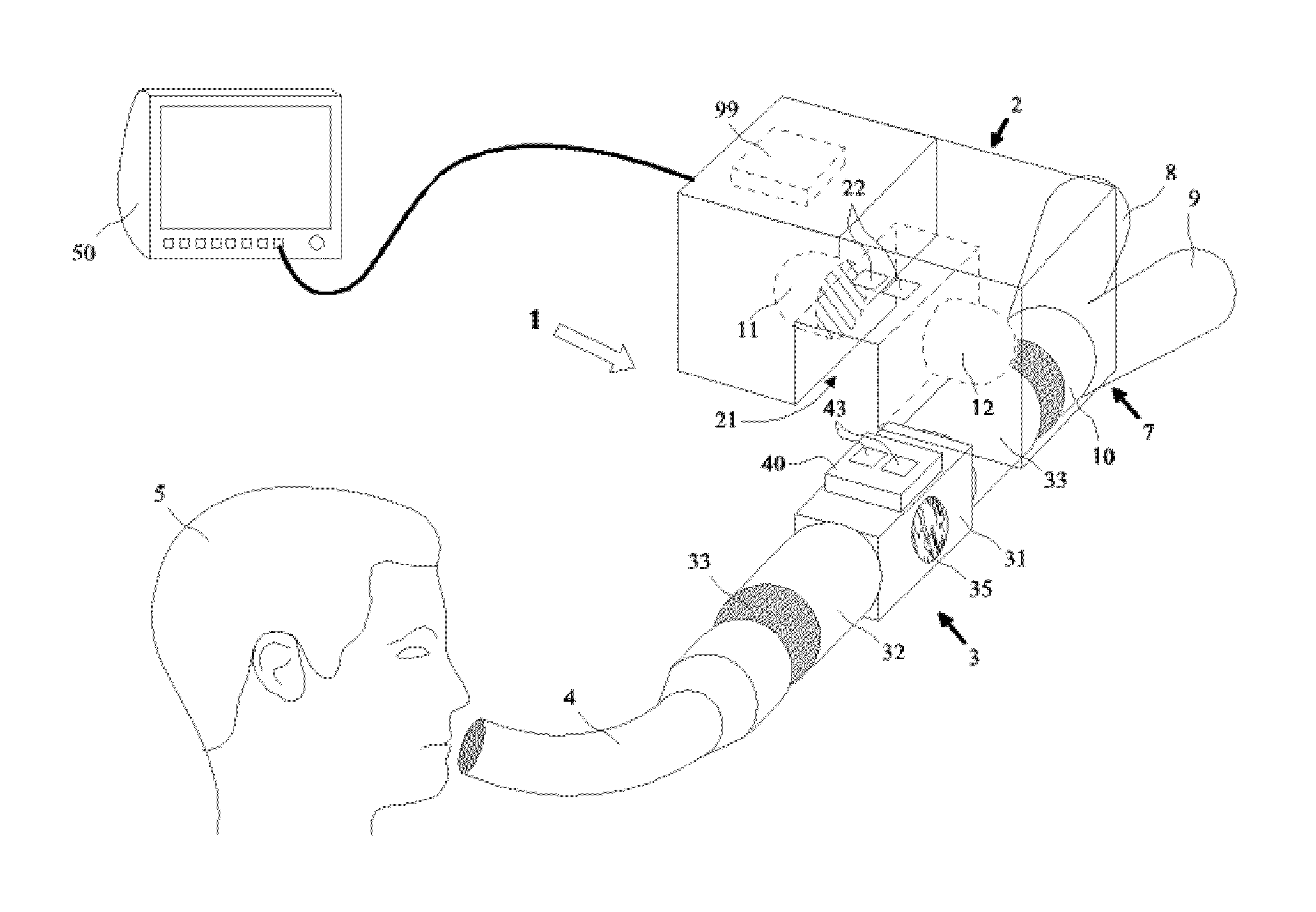
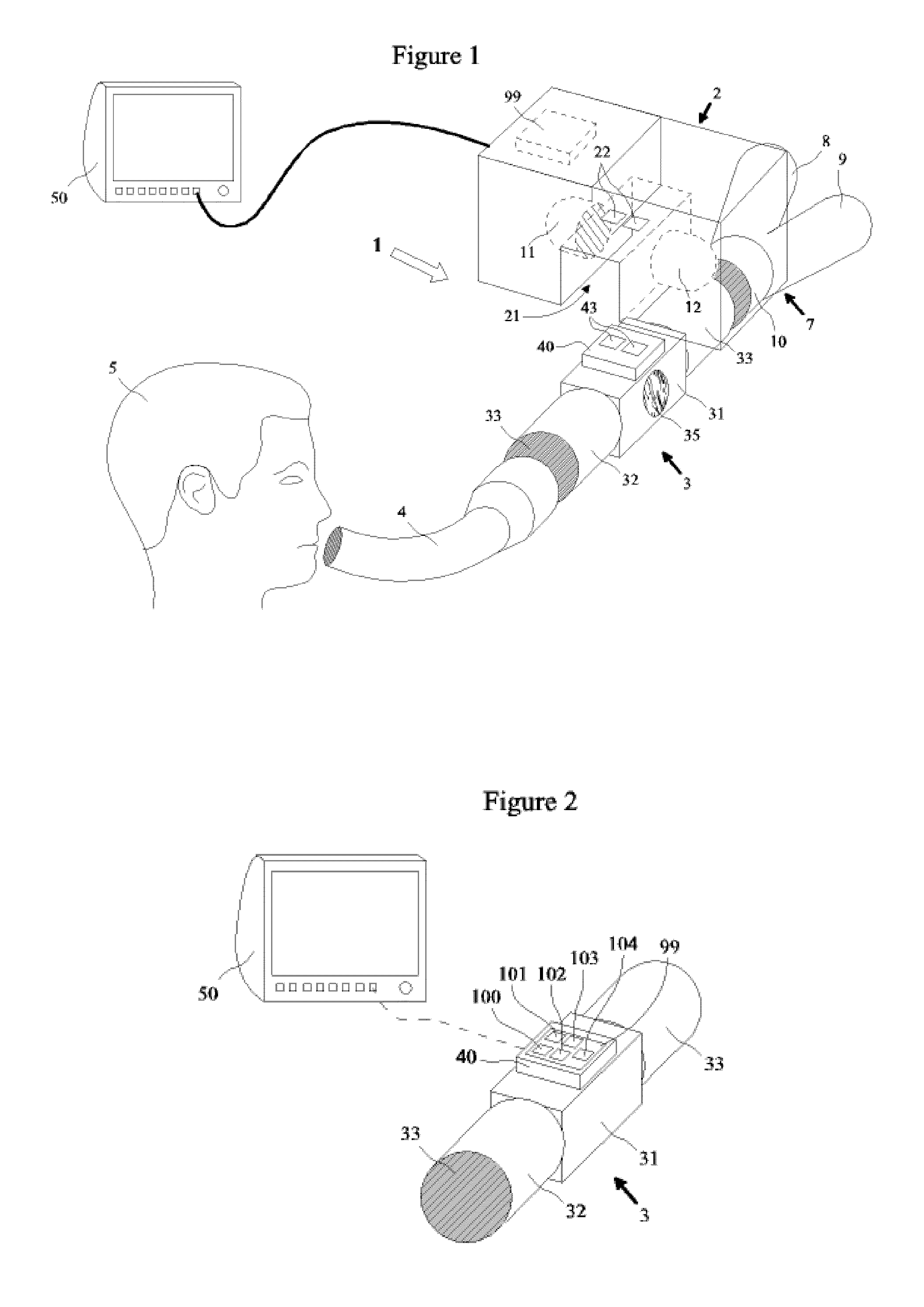
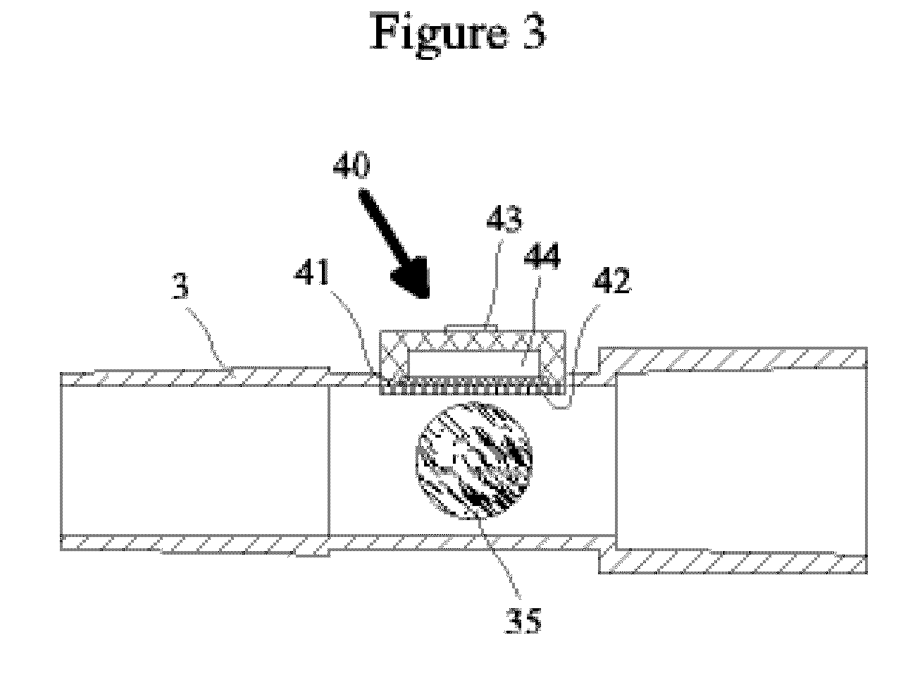
[0026]FIG. 1 shows a gas analyzing unit 1 comprising a gas analyzer 2 such as a main stream gas analyzer for making one of a qualitative or quantitative gas analysis of at least one respiratory gas like CO2 or Oxygen. and an airway adapter 3 in a typical operating environment where the gas analyzing unit 1 is connected through an endotracheal tube 4 to airways of a subject 5. The gas analyzing unit 1 may also be connected to a branching unit 7 such as a Y-piece having at least three limbs, one of them being an inhalation limb 8 for inspired gas, a second one being an expiration limb 9 for expired gas, a third one being a combined inspiration and expiration limb 10 for both inspired and expired gases. The inhalation limb 8 is connectabl...


PUM


Abstract

An airway adapter. The airway adapter has a sampling chamber for allowing a respiratory gas flow. The airway adapter also has a sensor for acquiring a signal needed for a respiratory gas analysis. The sensor is integrated into the airway adapter and which sensor comprises an electrolyte being in contact with the respiratory gas flowing in the sampling chamber and which electrolyte contact with the respiratory gas is a basis for respiratory gas analysis.

Description

CROSS-REFERENCE TO RELATED APPLICATIONS[0001]This application claims priority under 35 U.S.C. §119(a)-(d) or (f) to prior-filed, co-pending European patent application serial number 08396016.1, filed on Oct. 23, 2008, which is hereby incorporated by reference in its entirety.STATEMENT REGARDING FEDERALLY SPONSORED RESEARCH OR DEVELOPMENT[0002]Not ApplicableNAMES OF PARTIES TO A JOINT RESEARCH AGREEMENT[0003]Not ApplicableREFERENCE TO A SEQUENCE LISTING, A TABLE, OR COMPUTER PROGRAM LISTING APPENDIX SUBMITTED ON COMPACT DISC[0004]Not ApplicableBACKGROUND OF THE INVENTION[0005]1. Field of the Invention[0006]This disclosure relates generally to a gas analyzing unit and an airway adapter usable in the gas-analyzing unit.[0007]2. Description of Related Art[0008]During anesthesia or in critical care, patients are often mechanically ventilated instead of breathing spontaneously. The patient is connected to a patient circuit of a ventilator or an anesthesia machine by intubation: inserting ...

Claims


Application Information

Patent Timeline
IPC IPC(8): A61B5/097
CPCA61B5/083G01N33/497G01N21/3504A61B5/097
Inventor HAVERI, HEIKKI ANTTI MIKAEL
Owner GE HEALTHCARE FINLAND
Learn More