Method and a system for identifying gaseous effluents, and a facility provided with such a system

a gaseous effluent and system technology, applied in the direction of optical radiation measurement, instruments, spectrophotometry/monochromators, etc., can solve the problems of large space occupied by a mass gas analyzer with differential pumping, dissuasion of investment cost and saving, and low cost of optical analysis technique, etc.

Inactive Publication Date: 2003-11-04
ALCATEL LUCENT SAS
View PDF13 Cites 31 Cited by
  • Summary
  • Abstract
  • Description
  • Claims
  • Application Information

AI Technical Summary

Benefits of technology

Each of the sources makes it possible to generate plasma from the gases existing in the enclosure, to do so while the facility is in operation, and to do so from low pressures up to atmospheric pressure.
The ionization efficiency obtained by these types of plasma source is close to 10% for a pressure of 10.sup.-1 mbars, hence very high measurement accuracy is achieved.
Thus, the combined use of a plasma source that can operate at atmospheric pressure together with an optical emission spectrum analysis system, makes it possible to obtain continuous diagnosis of the gases situated inside a controlled-pressure enclosure.
The use of differential pumping is not necessary to the operation of the ionization source, and this reduces the volume of the gas analyzer, and therefore it can be integrated easily into the semiconductor facility (in series or via a standard coupling).
Finally, the cost of this optical analysis technique is low because it associates only one ionization source with an optical detector. This facilitates generalizing it on the vacuum lines of facilities used in the semiconductor industry.

Problems solved by technology

The problem encountered in implementing a gas analysis technique lies in the investment cost and the saving achieved by preventive detection of defects in comparison with the production costs and the quality costs generated by the processes.
Since a plurality of vacuum pumps and valves are used, the cost of a gas analyzer operating at high pressures (0.1 mbars to 1000 mbars) is six times higher than an RGA-type analyzer which analyzes the residual vacuum only; and thus its cost is dissuasive compared with the cost of the semiconductor manufacturing machine and with the quantitative and qualitative efficiency thereof.
In addition, the space occupied by a mass gas analyzer with differential pumping is large because such an analyzer incorporates several voluminous vacuum components.
That makes it difficult to integrate into current vacuum facilities which often comprise several manufacturing chambers.
That is why few vacuum facilities are equipped with gas analyzers in spite of demand from industry.

Method used


Image

  • Method and a system for identifying gaseous effluents, and a facility provided with such a system
  • Method and a system for identifying gaseous effluents, and a facility provided with such a system
  • Method and a system for identifying gaseous effluents, and a facility provided with such a system

Examples


Embodiment Construction

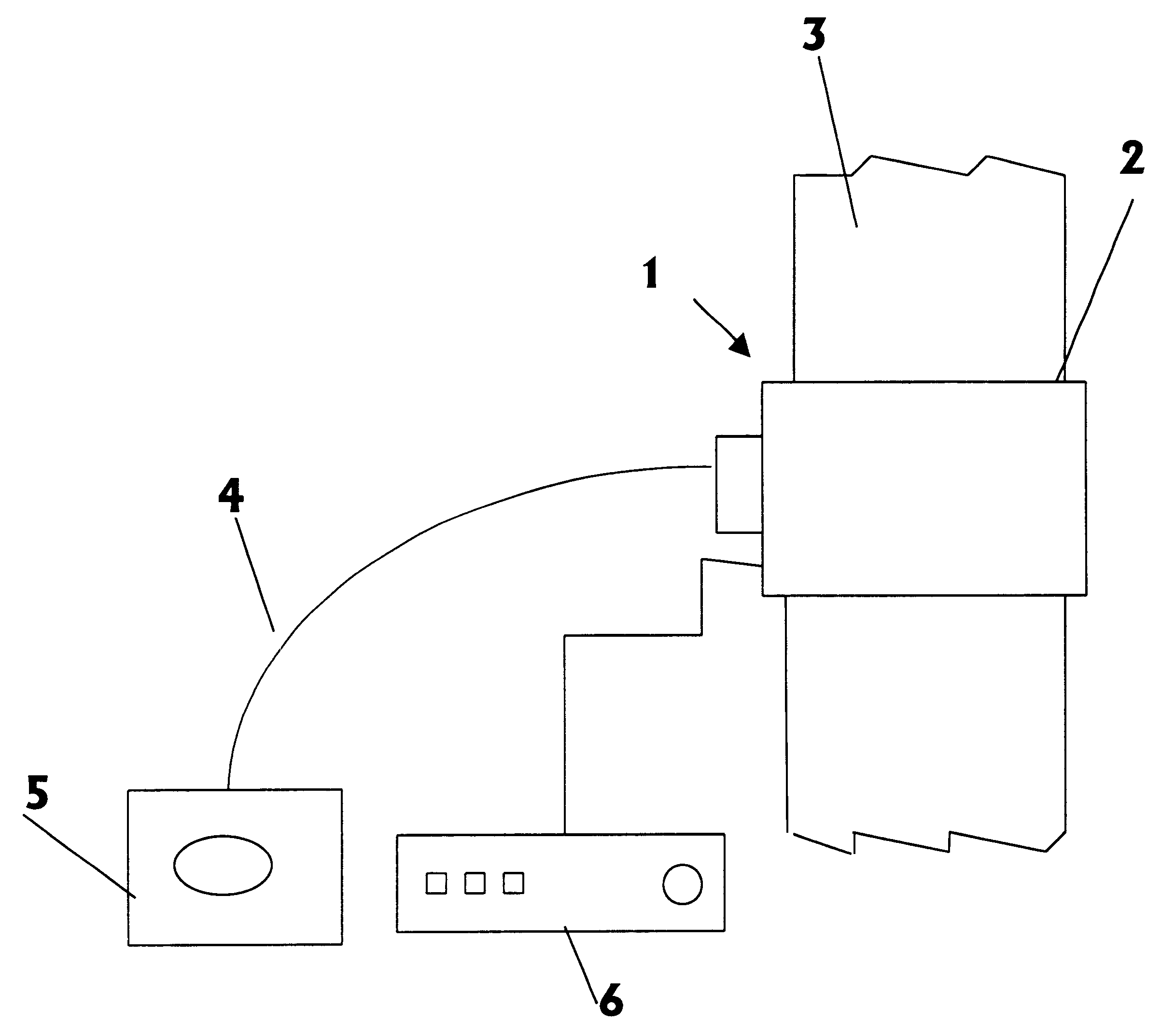
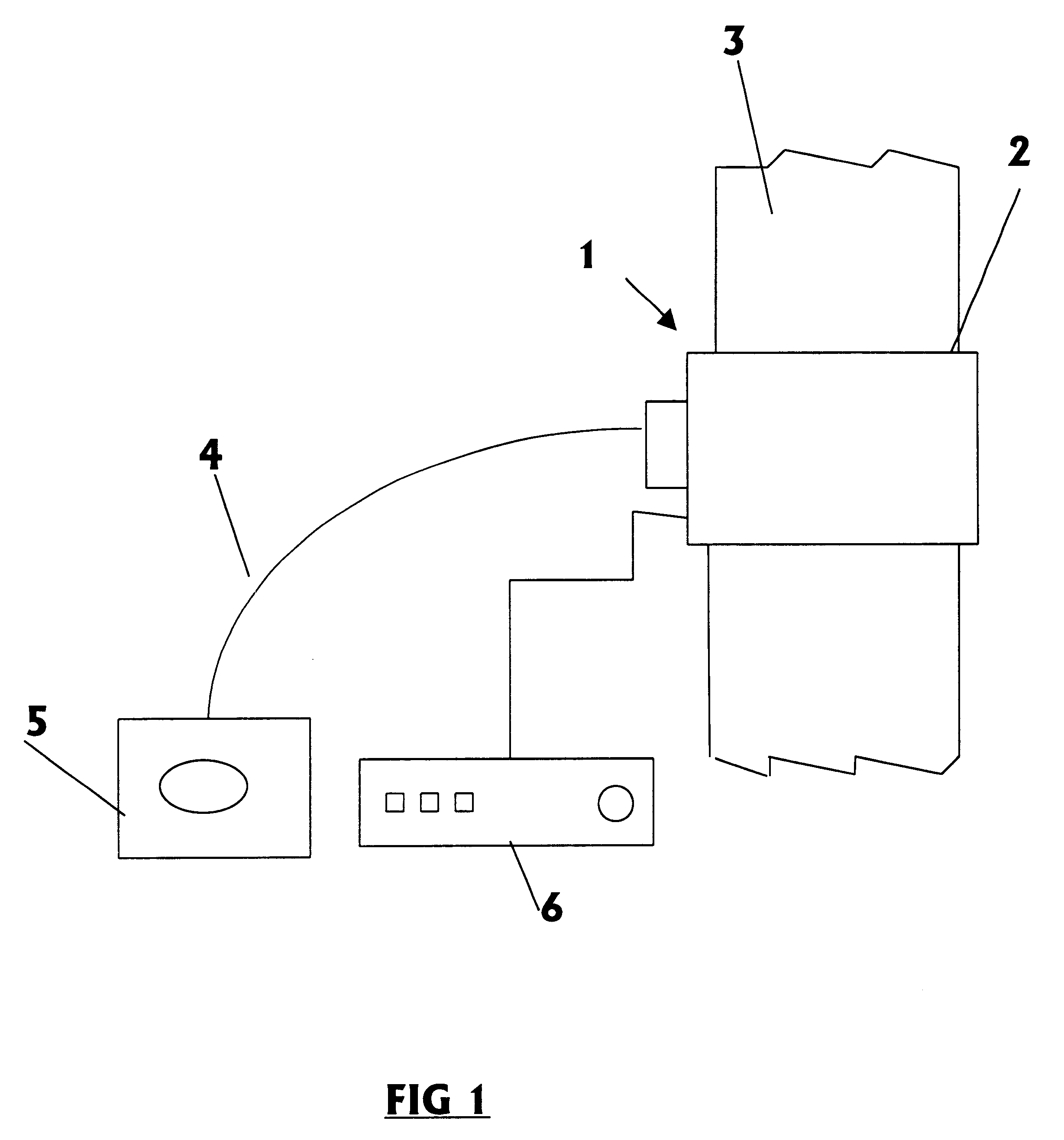
The gas analysis system 1 of the invention serves to analyze gaseous effluents contained in an enclosure 3 under controlled pressure. For example, the enclosure 3 may be a vacuum line 3 of a facility (not shown) for manufacturing semiconductor integrated circuits.

The operating principle of the gas analysis system 1 is based on ionizing the gases and on analyzing the radiation spectrum resulting from ionizing the gases.

For this purpose, the gas analysis system 1 includes apparatus for ionizing the gases to be analyzed, which apparatus is constituted by a dedicated plasma source 2 in contact with the gases in the enclosure 3, and generating a plasma from the gases to be analyzed. The plasma source 2 is powered by a generator 6 suited to the chosen type of plasma source 2.

In an embodiment, the plasma source 2 is a microwave source of the resonant cavity type or of the type using the surface wave propagation principle. in which case, the generator 6 is a microwave generator.

In another e...


PUM

PropertyMeasurementUnit
pressureaaaaaaaaaa
diameteraaaaaaaaaa
radiation spectrumaaaaaaaaaa

Abstract

The invention relates to a gas analysis system for analyzing gases in an enclosure under controlled pressure, which system comprises apparatus for ionizing the gases to be analyzed, and apparatus for analyzing the ionized gases. According to the invention the apparatus for ionizing the gases to be analyzed comprises a dedicated plasma source in contact with the gases contained in the enclosure and combined with a generator for generating a plasma from the gases to be analyzed; and the apparatus for analyzing the ionized gases comprises a radiation sensor situated in the vicinity of the zone in which the plasma is generated, and connected to an optical spectrometer for analyzing the variation of the radiation spectrum emitted by the generated plasma.

Description

The invention relates to a method and a system for analyzing gaseous effluents. More particularly, the invention relates to a method and a system for analyzing gaseous effluents in an enclosure under a controlled pressure. The invention also relates to an industrial facility including at least one controlled-pressure enclosure and a system for analyzing the gases contained in the controlled-pressure enclosure.The progress made in recent years in the semiconductor industry is essentially related to the integration of electronic circuits on components of a few square millimeters; this being done on silicon substrates that are increasingly large (diameter in the range 200 mm to 300 mm).The number of technological steps necessary to make such circuits is large (up to 400).Among such steps, the vacuum treatment steps are of essential importance both by their ability to produce continuously throughout the manufacturing process and also by their functions of satisfying the geometrical crit...

Claims


Application Information

Patent Timeline
Patent Type & Authority Patents(United States)
IPC IPC(8): G01N21/62G01N21/68C23C16/52G01N21/73
CPCG01N21/68
Inventor CHEVALIER, ERICMAQUIN, PHILIPPEBERNARD, ROLAND
Owner ALCATEL LUCENT SAS
Why Eureka
Try Eureka