System and method for gas analysis using photoacoustic spectroscopy

a technology of photoacoustic spectroscopy and gas analysis, applied in material analysis using wave/particle radiation, vibration measurement in solids, instruments, etc., can solve the problems of introducing significant moisture contamination, moisture presence, and currently available sensors that do not meet all the above requirements

Active Publication Date: 2008-06-12
LI COR
View PDF9 Cites 30 Cited by
  • Summary
  • Abstract
  • Description
  • Claims
  • Application Information

AI Technical Summary

Problems solved by technology

While ultra pure (water and other contaminant free) gases are sometimes available, chemical reactions, phase changes, and other effects often result in the presence of moisture in a gas supply line of a semiconductor fabrication system.
Currently available sensors do not meet all the aforementioned requirements.
As such, even very small leaks of ambient air into the gas distribution system may introduce significant moisture contamination.
Contaminants in these gases can diminish yields and degrade chip reliability.
Purity requirements for process gases will likely become even more strict as chip line widths continue to shrink.
As indicated, one common contaminant is water vapor which can distort manufacturing processes and thereby compromise device performance.
Moisture can create pitting, hazing, and stacking faults; cause resist patterns to fail; induce diodes and junctions to leak; and otherwise degrade the service lifetime of products which pass inspection and reach the marketplace.
Additionally, moisture will react with certain process gases, yielding acids which corrode gas handling equipment.
As corrosion advances, pipes, valves, mass flow meters, mass flow controllers, and other components can fail, causing equipment downtime.
Furthermore, corroded pipes release particles which enter the gas stream.
Moisture in arsine and phosphine lines may also contaminate the ultra-high-vacuum chambers used for doping wafers.
Water molecules in the chamber can make it impossible to draw a sufficiently high vacuum, forcing engineers to shut down the chamber and subject it to an extended bake.
Trace oxygen in the epitaxial layers can limit device performance.
The resulting incorporation of oxygen atoms can induce dislocations into the strained layers, which may degrade device performance and, subsequently, reliability.” O. Kermarrec et. al., Solid State Technology, 45(3).
Since none of the technologies available today can satisfy all of these criteria and therefore do not meet the needs of fab operators, it is not surprising that wafer fabs rarely deploy in-line monitors.
However, scientific and technological interest in the effect lay dormant for approximately 80 years in the absence of suitable light sources and microphones.
Widely deployable systems, however, will require compact and inexpensive light sources.
This system reportedly was able to detect moisture at levels of about 250 ppbv and would therefore appear to have come within a factor of about 25 of the minimum required sensitivity for semiconductor gases, but did not meet the criteria for industrial use in terms of size or cost.
The prior art also sought achieve maximum power transfer to the microphone, which I have found is undesirable since this inherently draws the maximum energy out of the cavity.
Moreover, the prior art did not realize that the detection sensitivity can be maximized by causing the microphone to form a integral part of the resonant system as opposed to considering only the cell itself without a microphone.
At the opening, moreover, there is radiation of sound into the surrounding medium which leads to the dissipation of acoustic energy and thus provides one source of frictional loss.
Because PAS cell sensitivity for most configurations is inversely proportional to volume, the large gas volumes in the two ends of the dumbbell tend to limit cell sensitivity.

Method used


Image

  • System and method for gas analysis using photoacoustic spectroscopy
  • System and method for gas analysis using photoacoustic spectroscopy
  • System and method for gas analysis using photoacoustic spectroscopy

Examples


Embodiment Construction

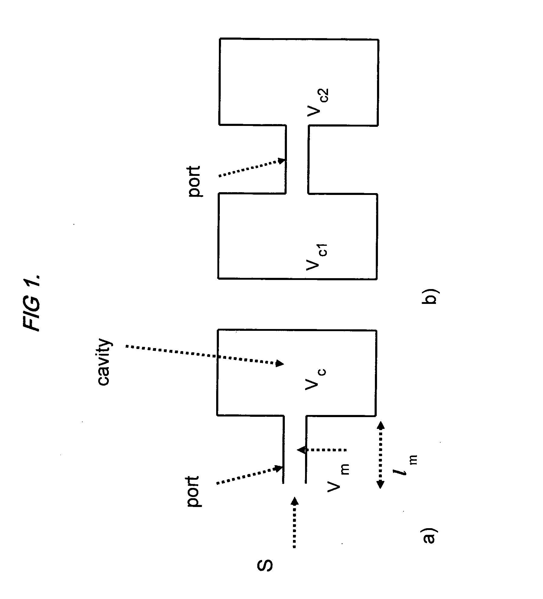
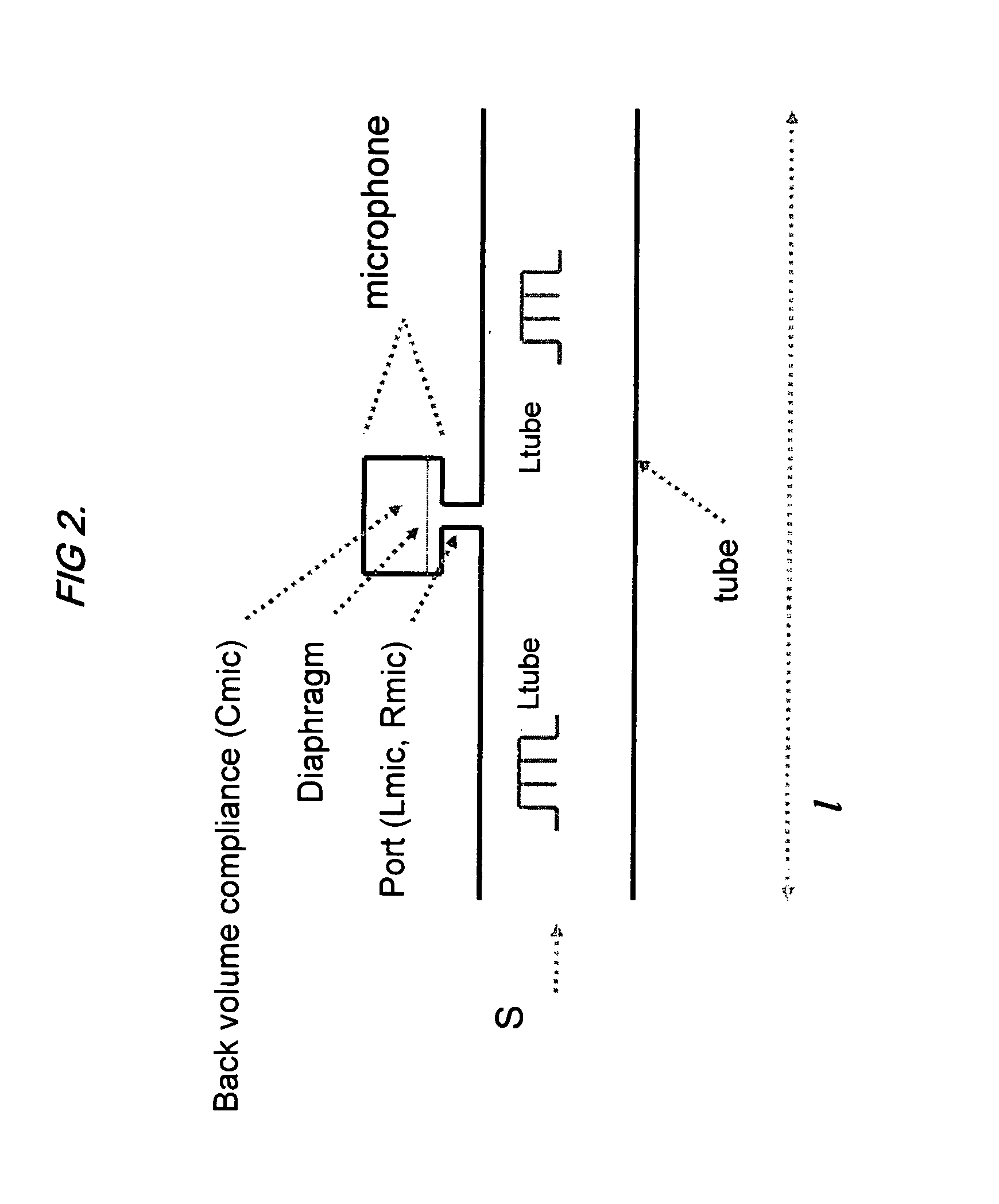
[0051]The present invention recognizes that the interaction between the microphone acoustic impedance and the cell acoustic impedance can be used to great benefit if a photoacoustic chamber is properly designed, as previously described and also in further detail below. In a first embodiment, a cell such as that shown in FIG. 2 has a microphone inside a tube. The lowest order resonance for this configuration has an analogous electrical circuit as shown in FIG. 4. The elements corresponding to the microphone are labeled with the subscript “mic”. The microphone can be represented by a series LRC circuit and at low frequencies the tube can be represented as an air mass just as the port is represented in FIG. 1a. At resonance the various elements of the network in FIG. 4 can be reduced to an equivalent circuit as shown in FIG. 3a). The circuit of FIG. 3a) is applicable to any parallel resonant network, including Helmholtz resonators. The preferred design of a PAS cell in accordance with ...


PUM

PropertyMeasurementUnit
lengthaaaaaaaaaa
lengthaaaaaaaaaa
volumeaaaaaaaaaa

Abstract

A system and method for analyzing a target analyte gas concentration using a photoacoustic spectroscopy cell comprising:i) a modulatable light source which provides optical radiation at an absorption wavelength of a target analyte;ii) a resonant acoustic chamber for containing said analyte;iii) a microphone positioned within said chamber whereby the acoustic reactance of the microphone is a substantial factor in determining the acoustic resonant frequency of the acoustic chamber and where the magnitude of the acoustic reactance of the microphone is at least two times the acoustic resistance of the microphone.

Description

RELATED APPLICATIONS[0001]This application claims priority from co-pending, commonly assigned application Ser. No. 11 / 485,129 filed 12 Jul. 2006.FIELD OF THE INVENTION[0002]The present invention relates generally to the field of analyte detection and concentration analysis and to an improved apparatus for performing same. In one preferred embodiment, the present invention relates especially to gas contaminant detection, e.g., trace moisture in a semiconductor process gas.BACKGROUND OF THE INVENTION[0003]As semiconductor technology advances and device sizes shrink, the impact of contaminants in the gases used to fabricate these devices becomes increasingly important. Many specialty gases are used in the production of semiconductor devices. For example, a major source of contamination in the chip fabrication process is the presence in process gases of trace amounts, e.g., on the order of tens of parts per billion by volume (ppbv), of water. While ultra pure (water and other contaminan...

Claims


Application Information

Patent Timeline
Patent Type & Authority Applications(United States)
IPC IPC(8): G01N21/84
CPCG01N2291/02872G01N21/1702G01N2021/1704
Inventor RIDDLE, ALFRED
Owner LI COR
Why Eureka
Try Eureka