Gas analysis device and method

A gas analysis and gas analyzer technology, which is used in sampling devices, analytical materials, semiconductor/solid-state device testing/measurement, etc., can solve the problems that the system cannot meet the test requirements and calibration requirements, and achieve the effect of ensuring the test accuracy.

Active Publication Date: 2014-01-01
RAINBOW SOURCE LASER RSLASER
View PDF4 Cites 35 Cited by
  • Summary
  • Abstract
  • Description
  • Claims
  • Application Information

AI Technical Summary

Benefits of technology

This patented technology allows an improved gas analyzer that uses regular checks or adjustments made after each use over its lifetime. By doing this it ensures accurate results even at very low levels of impurities such as oxygen (O2)) inside the instrument's components. Additionally, there may also include protection against damage caused from high temperatures when testing certain materials like silicon wafers used in semiconductor manufacturing processes. Overall, these technical improvements improve performance and reliability of gas analyzation devices while maintain their effectiveness throughout their lifespan.

Problems solved by technology

This technical problem addressed in this patents relates to improving the performance and reliability of gas analyzers (gas concentration measurement) during high temperature environments where harmful chemical species are present due to their impact on the transmitted signal or interference between signals. Current systems require external sources like an oven at temperatures above 150 degrees Celsius, making them unsuitable for long term monitoring without frequent replacements over time. Therefore, new methods must integrate into these systems while ensuring they operate correctly even if exposed to harsh environmental factors.

Method used


Image

  • Gas analysis device and method
  • Gas analysis device and method

Examples


Embodiment 1

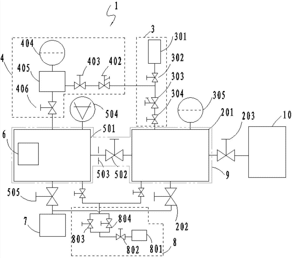
[0042] like figure 1 As shown, this embodiment discloses a gas analysis device for analyzing the gas in the chamber to be measured, including: a sampling chamber 201, an analysis chamber 501, a gas analyzer 6, and a calibration module. The sampling chamber 201 is connected to the chamber to be tested 10 through the first valve 203, and is used to introduce the sample gas from the chamber to be tested 10 and the standard gas provided by the calibration module. Multiple chambers are tested separately in situ. The analysis chamber 501 is connected to the sampling chamber 201 through the second valve. The analysis chamber 501 is provided with a vacuum gauge 504 for monitoring the vacuum degree of the analysis chamber 501. The vacuum degree of the analysis chamber 501 should meet the working requirements of the gas analyzer 6, otherwise It will burn out the gas analyzer 6. The gas analyzer 6 is set in the analysis chamber 501 for analyzing and testing the gas to be analyzed; the ...

Embodiment 2

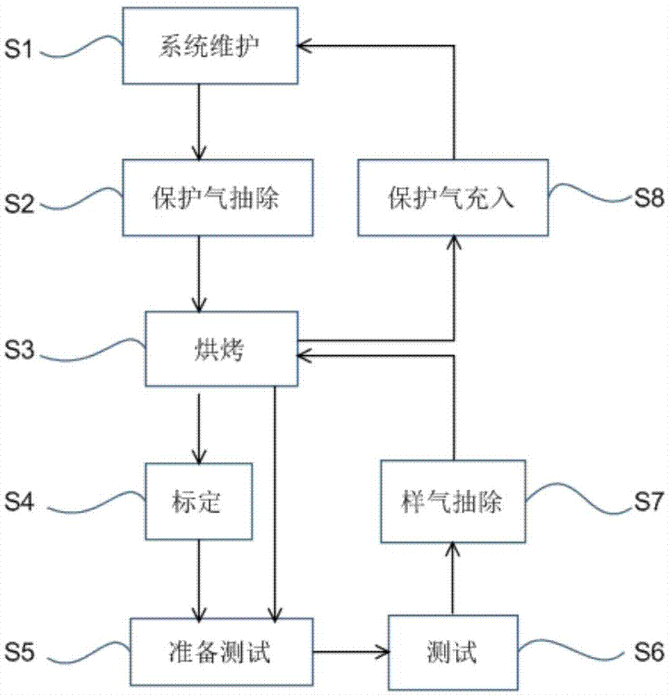
[0064] like figure 2 As shown, the gas analysis method provided in this embodiment takes the dynamic calibration method as an example, and specifically includes the following steps:

[0065] S1, system maintenance;

[0066] The initial state of the gas analysis device is the maintenance state, filled with protective gas, and the valves are closed;

[0067] S2, shielding gas extraction;

[0068] Open the first pumping valve 505 between the analysis chamber 501 and the second pumping valve 202 between the sampling chamber 201 on the pump group, and the second valve (valve plate) between the analysis chamber 501 and the sampling chamber 201 502, 503), extract the protective gas in the analysis chamber 501 and the sampling chamber 201;

[0069] S3, baking;

[0070] The analysis chamber 501 and the sampling chamber 201 are baked and degassed by the heater 9 arranged on the analysis chamber 501 and the sampling chamber 201;

[0071] S4, calibration;

[0072] Treat that baking...

Embodiment 3

[0082] The gas analysis method provided in this embodiment takes the static calibration method as an example, and specifically includes the following steps:

[0083] S1, system maintenance;

[0084] The initial state of the gas analysis device is the maintenance state, filled with protective gas, and the valves are closed;

[0085] S2, shielding gas extraction;

[0086] Open the first pumping valve 505 between the analysis chamber 501 and the second pumping valve 202 between the sampling chamber 201 on the pump group, and the second valve (valve plate) between the analysis chamber 501 and the sampling chamber 201 502, 503), extract the protective gas in the analysis chamber 501 and the sampling chamber 201;;

[0087] S3, baking;

[0088] The analysis chamber 501 and the sampling chamber 201 are baked and degassed by the heater 9 arranged on the analysis chamber 501 and the sampling chamber 201;

[0089] S4, calibration;

[0090] After the baking program is finished, open ...


PUM


Abstract

The invention provides a gas analysis device with an in-situ calibration function. The gas analysis device comprises a sampling chamber, an analysis chamber, a gas analyzer and a calibration module, wherein the sampling chamber is connected with a to-be-detected chamber through a first valve and used for leading in sample gas in the to-be-detected chamber; the analysis chamber is connected with the sampling chamber through a second valve, and a vacuum gauge tube is arranged on the analysis chamber and used for monitoring the degree of vacuum of the analysis chamber; the gas analyzer is arranged in the analysis chamber and used for analyzing and testing to-be-analyzed gas; the calibration module is used for providing standard gas for the gas analyzer and quantificationally calibrating the gas analysis device. The invention further provides a gas analysis method. According to the invention, the gas analysis device is periodically calibrated through the calibration module, bakeout degassing is performed through a heater, gas sweeping and protective gas filling are performed through a sweeping and degassing module, a system is enabled to maintain favorable testing background, testing accuracy is guaranteed, gas strength testing at the level of part per billion can be realized, and the gas analysis device is especially suitable for gas analysis and detection in EUV vacuum environment.

Description


Claims


Application Information

Patent Timeline
Owner RAINBOW SOURCE LASER RSLASER
Why Eureka
Try Eureka