Gas analysis device and method
A technology of gas analysis and gas analyzer, which is applied in the direction of sampling device, analysis material, semiconductor/solid-state device testing/measurement, etc. It can solve the problems that the system cannot meet the test requirements and calibration requirements, and achieve the effect of ensuring the accuracy of the test
- Summary
- Abstract
- Description
- Claims
- Application Information
AI Technical Summary
Problems solved by technology
Method used
Image
Examples
Embodiment 1
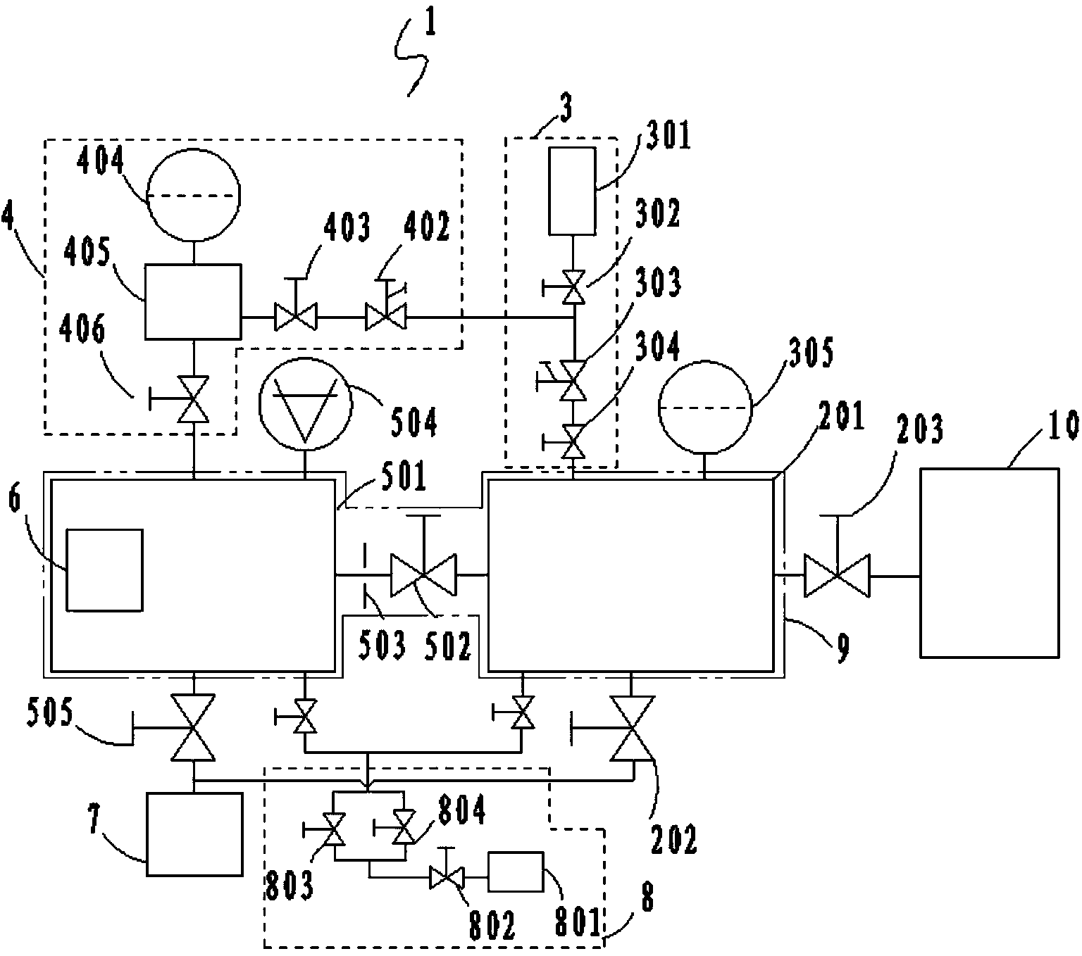
[0042] Such as figure 1 As shown, this embodiment discloses a gas analysis device for analyzing the gas in the chamber to be measured, including: a sampling chamber 201, an analysis chamber 501, a gas analyzer 6, and a calibration module. The sampling chamber 201 is connected to the chamber to be tested 10 through the first valve 203, and is used to introduce the sample gas from the chamber to be tested 10 and the standard gas provided by the calibration module. Multiple chambers are tested separately in situ. The analysis chamber 501 is connected to the sampling chamber 201 through the second valve. The analysis chamber 501 is provided with a vacuum gauge 504 for monitoring the vacuum degree of the analysis chamber 501. The vacuum degree of the analysis chamber 501 should meet the working requirements of the gas analyzer 6, otherwise It will burn out the gas analyzer 6. The gas analyzer 6 is set in the analysis chamber 501 for analyzing and testing the gas to be analyzed; t...
Embodiment 2
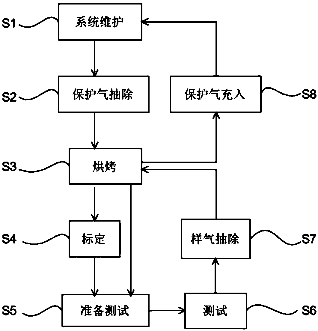
[0064] like figure 2 As shown, the gas analysis method provided in this embodiment takes the dynamic calibration method as an example, and specifically includes the following steps:
[0065] S1, system maintenance;
[0066] The initial state of the gas analysis device is the maintenance state, filled with protective gas, and the valves are closed;
[0067] S2, shielding gas extraction;
[0068] Open the first pumping valve 505 between the analysis chamber 501 and the second pumping valve 202 between the sampling chamber 201 on the pump group, and the second valve (valve plate) between the analysis chamber 501 and the sampling chamber 201 502, 503), extract the protective gas in the analysis chamber 501 and the sampling chamber 201;
[0069] S3, baking;
[0070] The analysis chamber 501 and the sampling chamber 201 are baked and degassed by the heater 9 arranged on the analysis chamber 501 and the sampling chamber 201;
[0071] S4, calibration;
[0072] Treat that baking...
Embodiment 3
[0082] The gas analysis method provided in this embodiment takes the static calibration method as an example, and specifically includes the following steps:
[0083] S1, system maintenance;
[0084] The initial state of the gas analysis device is the maintenance state, filled with protective gas, and the valves are closed;
[0085] S2, shielding gas extraction;
[0086] Open the first pumping valve 505 between the analysis chamber 501 and the second pumping valve 202 between the sampling chamber 201 on the pump group, and the second valve (valve plate) between the analysis chamber 501 and the sampling chamber 201 502, 503), extract the protective gas in the analysis chamber 501 and the sampling chamber 201;;
[0087] S3, baking;
[0088] The analysis chamber 501 and the sampling chamber 201 are baked and degassed by the heater 9 arranged on the analysis chamber 501 and the sampling chamber 201;
[0089] S4, calibration;
[0090] After the baking program is finished, open ...
PUM
 Abstract
Description
Claims
Application Information
 - R&D
- Intellectual Property
- Life Sciences
- Materials
- Tech Scout
- Unparalleled Data Quality
- Higher Quality Content
- 60% Fewer Hallucinations
Browse by: Latest US Patents, China's latest patents, Technical Efficacy Thesaurus, Application Domain, Technology Topic, Popular Technical Reports.
© 2025 PatSnap. All rights reserved.Legal|Privacy policy|Modern Slavery Act Transparency Statement|Sitemap|About US| Contact US: help@patsnap.com


