Radio frequency identification electronic label antenna complex impedance test device and method

A technology of electronic tags and testing devices, which is applied in the field of electronic information, and can solve problems affecting the accuracy of test results, complex test structure results, and coaxial cable impedance mismatches, etc.

Active Publication Date: 2010-06-23
INST OF AUTOMATION CHINESE ACAD OF SCI
View PDF0 Cites 16 Cited by
  • Summary
  • Abstract
  • Description
  • Claims
  • Application Information

AI Technical Summary

Problems solved by technology

In addition, the port of the electronic tag antenna to be tested is generally set to complex impedance at the operating frequency, and there is an impedance mismatch with the coaxial cable, which seriously affects the accuracy of the test results
The general test device for the electronic tag antenna to be tested is: load an impedance matching circuit and a balun device on the port, the test structure is complex and has different negligible effects on the results

Method used


Image

  • Radio frequency identification electronic label antenna complex impedance test device and method
  • Radio frequency identification electronic label antenna complex impedance test device and method
  • Radio frequency identification electronic label antenna complex impedance test device and method

Examples


Embodiment Construction

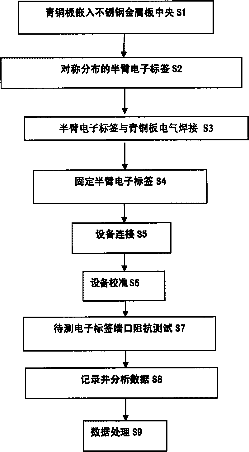
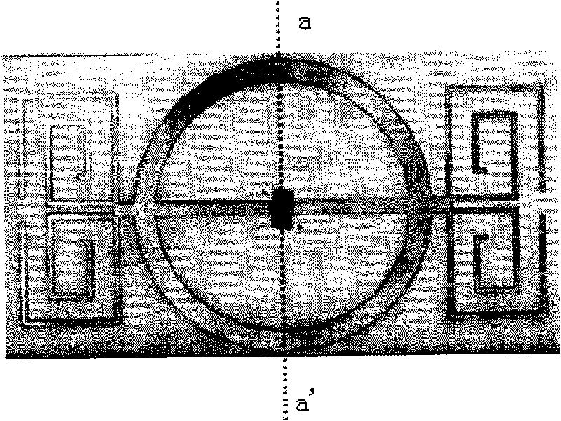
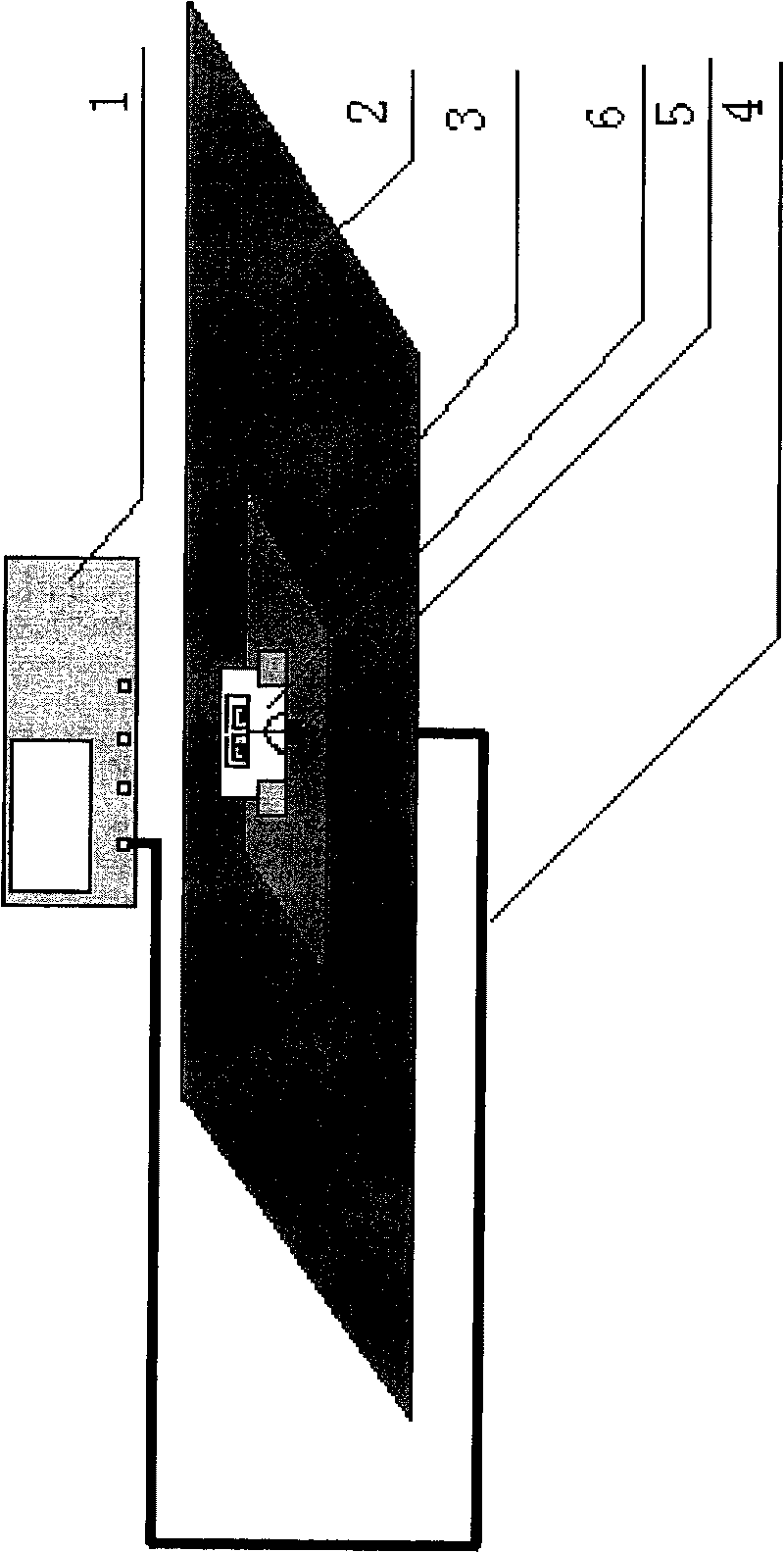
[0027] In order to make the object, technical solution and advantages of the present invention clearer, the present invention will be described in further detail below in conjunction with specific embodiments and with reference to the accompanying drawings. Below, we use an example to illustrate the measurement of the electronic tag antenna complex impedance device to be tested by the mirror image method.

[0028] The radio frequency identification system electronic tag antenna to be tested stands vertically near a piece of conductor, the energy radiated toward the conductor is reflected, and the synthesized field is the vector sum of the direct wave and the reflected wave. It can also be considered that the latter is not caused by reflections, but by a mirrored antenna below the surface of the conductor. The 1 / 4 wavelength antenna fed by the end point cooperates with its mirror image antenna to form a half-wave dipole antenna, but because there is no reflection field in the l...


PUM


Abstract

The invention relates to a radio frequency identification electronic label antenna complex impedance test device and a method. A cable is respectively and electrically connected with a vector network analyzer and a second metal plate, the second metal plate is embedded inside a first metal plate, a core of a switching port is electrically connected with a feed port of a semi-arm electronic label antenna, and a sheath of the switching port is connected with the second metal plate in a short-circuit way. By utilizing the principle of an image method and testing the impedance of the semi-arm antenna port, the test difficulty for the balance feed-form antenna can be solved. Compared with the steps of a balance/imbalance converter and a matching network required for testing the balance feed-form antenna impedance, the test procedure of the device is simple and convenient, and the device has economic benefit while ensuring the test precision.

Description

technical field [0001] The invention belongs to the technical field of electronic information, and mainly relates to a device and method for measuring the impedance of an electronic tag antenna of a radio frequency identification (RFID) system. Background technique [0002] Electronic tag antennas are generally in the form of balanced feeding. If feeding with a coaxial cable, a balanced / unbalanced converter needs to be added between the antenna and the cable, which is commonly called a balun. In addition, the complex impedance measurement of the electronic tag antenna needs to add a matching network before the balun to convert the impedance of the antenna to 50 ohms, so as to realize the accurate measurement of the electronic tag antenna. The conventional measurement method is not only cumbersome, but also expensive. Moreover, due to the influence of surrounding test devices on the antenna port, the accuracy of the test results needs to be improved. [0003] During the meas...

Claims


Application Information

Patent Timeline
Patent Type & Authority Applications(China)
IPC IPC(8): G01R27/02
Inventor 王宏伟谭杰朱智源
Owner INST OF AUTOMATION CHINESE ACAD OF SCI
Why Eureka
Try Eureka