Water injection well wellhead test blowout preventer

A technology for blowout prevention devices and water injection wells, which can be applied to wellbore/well components, measurement, drilling equipment, etc., which can solve the problems of uncontrollable steel wire rushing speed, difficulty in sealing high pressure of packing mechanism, and high field operation intensity, etc., to achieve Improve the test accuracy and pass rate of water distribution, solve the test problems of high-pressure water injection wells, and improve the effect of test success rate

Inactive Publication Date: 2018-04-27
CHINA PETROLEUM & CHEM CORP +1
View PDF5 Cites 0 Cited by
  • Summary
  • Abstract
  • Description
  • Claims
  • Application Information

AI Technical Summary

Problems solved by technology

[0002] At present, the existing wellhead blowout prevention technology for water injection well testing is mainly aimed at water injection wells with normal pressure (water injection pressure ≤ 25MPa). During the layered test of water wells, there were problems such as imperfect supporting technology, specifically the following aspects: the packing mechanism was difficult to seal high pressure, the spray leakage was serious during the process of lifting and lowering the instrument, and it was easy to cause environmental pollution; Difficult to disassemble and heavy on-site operations; the high pressure at the wellhead acts on the sealing packing to compress the steel wire, and at the same time generates an upward force on the steel wire, which makes it difficult to lift and lower the test instrument. When going down, it needs to overcome the upward force and compression force, and the test instrument relies on weight It is difficult to go down, and workers need to climb up and manually transport; when lifting, the upward force is converted into power, so that the speed of the steel wire rushing out cannot be controlled, and the steel wire cannot be retracted synchronously with the winch and scattered on the ground
[0003] The new type of blowout preventer retrieved from the literature is only equipped with a vent valve on the upper wall of the blowout preventer body. When the wellhead pressure is high, the pressure relief control can be performed, but there are still disadvantages of leakage and pollution of the environment.

Method used


Image

  • Water injection well wellhead test blowout preventer

Examples


Embodiment Construction

[0021] The detailed description and technical content of the present invention are described below with the accompanying drawings, but the accompanying drawings are only provided for reference and description, and are not intended to limit the present invention.

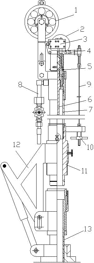
[0022] Refer to attached figure 1 , the wellhead test blowout preventer of the water injection well mainly includes the blowout preventer 7, the upper end of the blowout preventer is provided with a blowout preventer 5, the lower end is connected with the sealing plug 11, the empty sleeve is lifted after the blowout preventer and the sealing plug are connected into one The device is installed or disassembled on the wellhead through the lifting device, and the blowout box is equipped with a driving device for lowering and pulling the test instrument. A throttling tube 6 is arranged at the inner lower end of the blowout prevention box. One side of the blowout prevention box is also connected with a discharge pipeline ...


PUM


Abstract

The invention discloses a blowout preventer for wellhead testing of water injection wells, which mainly includes a blowout preventer. A blowout preventer is arranged at the upper end of the blowout preventer, and a sealing plug is connected to the lower end of the blowout preventer. The lifting device is installed or disassembled on the wellhead through the lifting device, and the blowout box is covered with a driving device for lowering and pulling the testing instrument. The device will effectively improve the test success rate of high-pressure water injection wells, and at the same time improve the test accuracy and water distribution qualification rate; solve the problem of high-pressure water injection well testing, and also has high promotion and application value in normal pressure water injection well testing. In a word, it has the following characteristics: 1) The blowout preventer is lifted by ground hydraulic pressure, which eliminates the need for workers to climb up or crane operations; 2) The use of gap leakage and pressure reduction and secondary self-sealing blowout prevention reduces wellhead leakage; 3) The motor drives the steel wire to overcome the underground high pressure and forcefully descends and automatically transports continuously.

Description

technical field [0001] The invention relates to wellhead sealing and blowout prevention technology during testing and deployment of water injection wells in oil fields, in particular to a wellhead testing blowout prevention device for water injection wells. Background technique [0002] At present, the existing wellhead blowout prevention technology for water injection well testing is mainly aimed at water injection wells with normal pressure (water injection pressure ≤ 25MPa). During the layered test of water wells, there were problems such as imperfect supporting technology, specifically the following aspects: the packing mechanism was difficult to seal high pressure, the spray leakage was serious during the process of lifting and lowering the instrument, and it was easy to cause environmental pollution; Difficult to disassemble and heavy on-site operations; the high pressure at the wellhead acts on the sealing packing to compress the steel wire, and at the same time gener...

Claims


Application Information

Patent Timeline
Patent Type & Authority Patents(China)
IPC IPC(8): E21B33/06E21B47/00E21B19/14
Inventor 孙金峰张一羽赵剑锋王宏万马艳洁田忠进辛林涛唐高峰李世文崔玉海
Owner CHINA PETROLEUM & CHEM CORP
Why Eureka
Try Eureka