
Minimally invasive method for delivery and positioning of intervertebral disc implants

a technology for intervertebral discs and implants, applied in the field of minimally invasive devices and methods for delivering implants to intervertebral discs, can solve the problems of limiting the size and ease of implant placement, and presenting challenges to precise and minimally invasive delivery

Inactive Publication Date: 2006-11-09
INTRINSIC THERAPEUTICS
View PDF29 Cites 47 Cited by
  • Summary
  • Abstract
  • Description
  • Claims
  • Application Information

AI Technical Summary

Benefits of technology

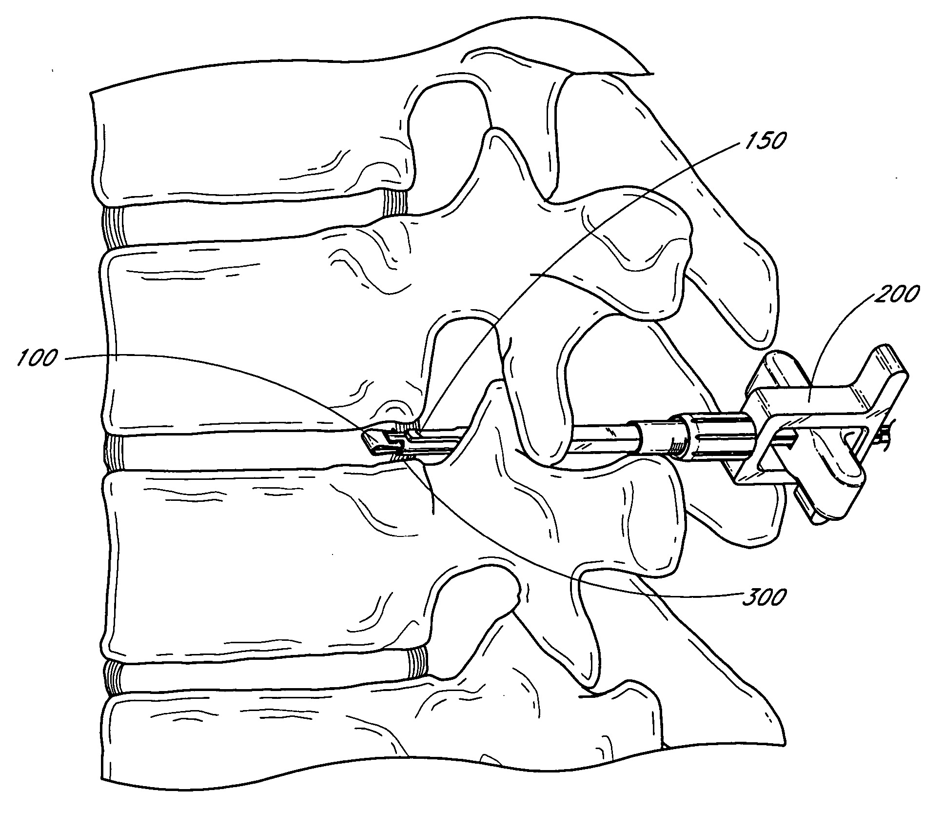
[0016] In yet another embodiment, a method of delivering a medical device (such as an implant) in an intervertebral disc along an innermost surface of an anulus of the disc is provided. In one embodiment, the method comprises inserting the implant through and beyond the innermost surface of the anulus, retracting the implant toward the innermost surface of the anulus, and deflecting at least a portion of the implant against the innermost surface of the anulus, thereby causing the implant to advance laterally along said surface.
[0017] In yet another embodiment, a method of delivering a medical device (such as an implant) in an intervertebral disc along an innermost surface of an anulus of the disc is provided. In one embodiment, the method comprises inserting the implant within the disc and beyond the innermost surface of the anulus, retracting the implant toward the innermost surface of the anulus, and deflecting at least a portion of the implant against the innermost surface of the anulus, thereby causing the implant to advance laterally along said surface. In one embodiment, the implant is expanded. In some embodiments, the method further comprises simultaneously retracting and deflecting the implant. In sever embodiments, the method further comprises simultaneously retracting and deflecting the implant in a synchronized manner. In a preferred embodiment, the method comprises rotating the implant.

Problems solved by technology

Certain physiological environments present challenges to precise and minimally invasive delivery.
Also, the difficulty and danger of the implantation procedure itself, due to the proximity of the spinal cord, limits the size and ease of placement of the implant.

Method used


Image

  • Minimally invasive method for delivery and positioning of intervertebral disc implants
  • Minimally invasive method for delivery and positioning of intervertebral disc implants
  • Minimally invasive method for delivery and positioning of intervertebral disc implants

Examples


Embodiment Construction

[0027] Several embodiments of the invention will be discussed herein through the demonstration of its use in the spine, with particular emphasis on intervertebral disc treatment. One of skill in the art will certain understand that several embodiments of the invention can be used to access or treat other sites in the body.

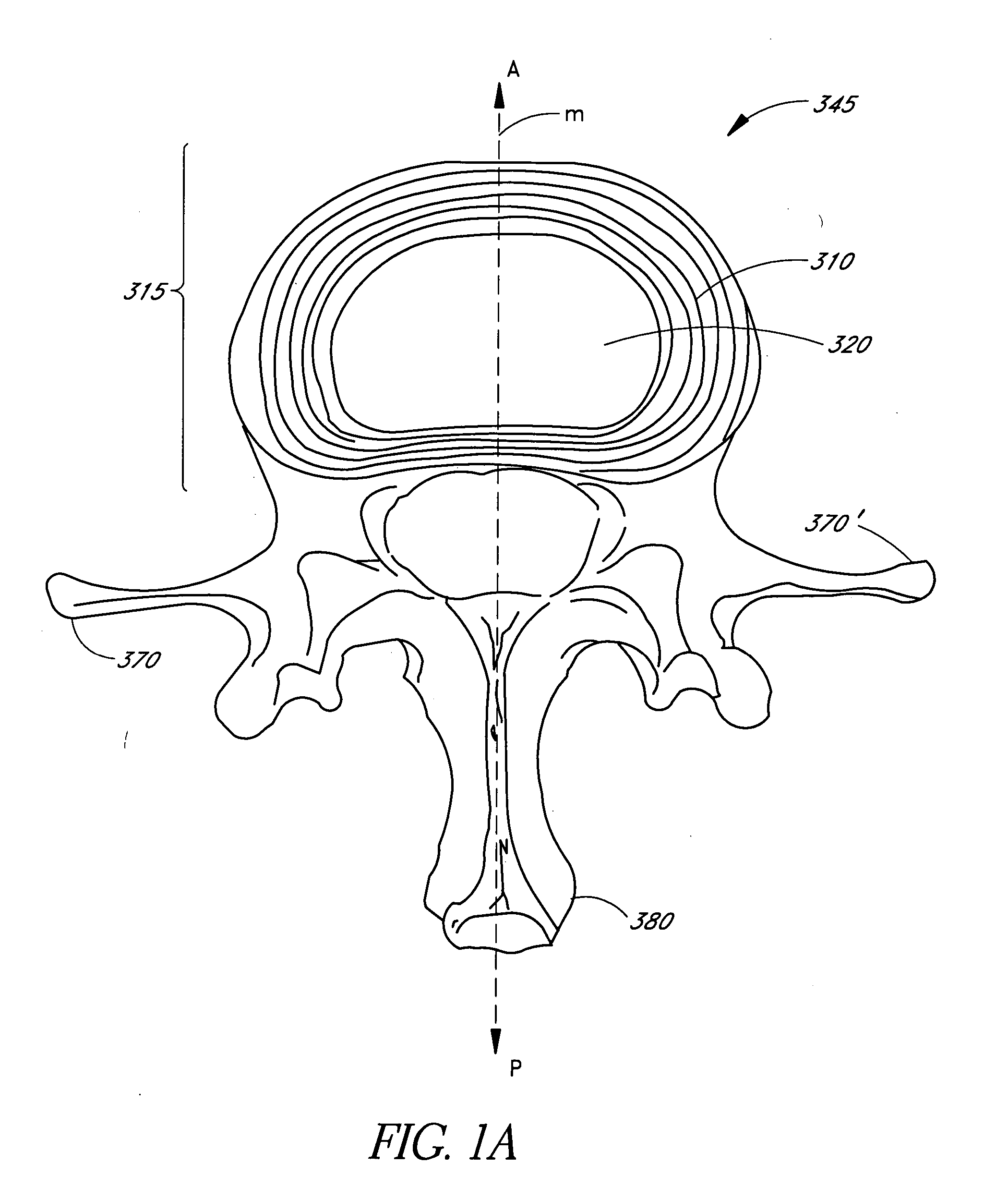
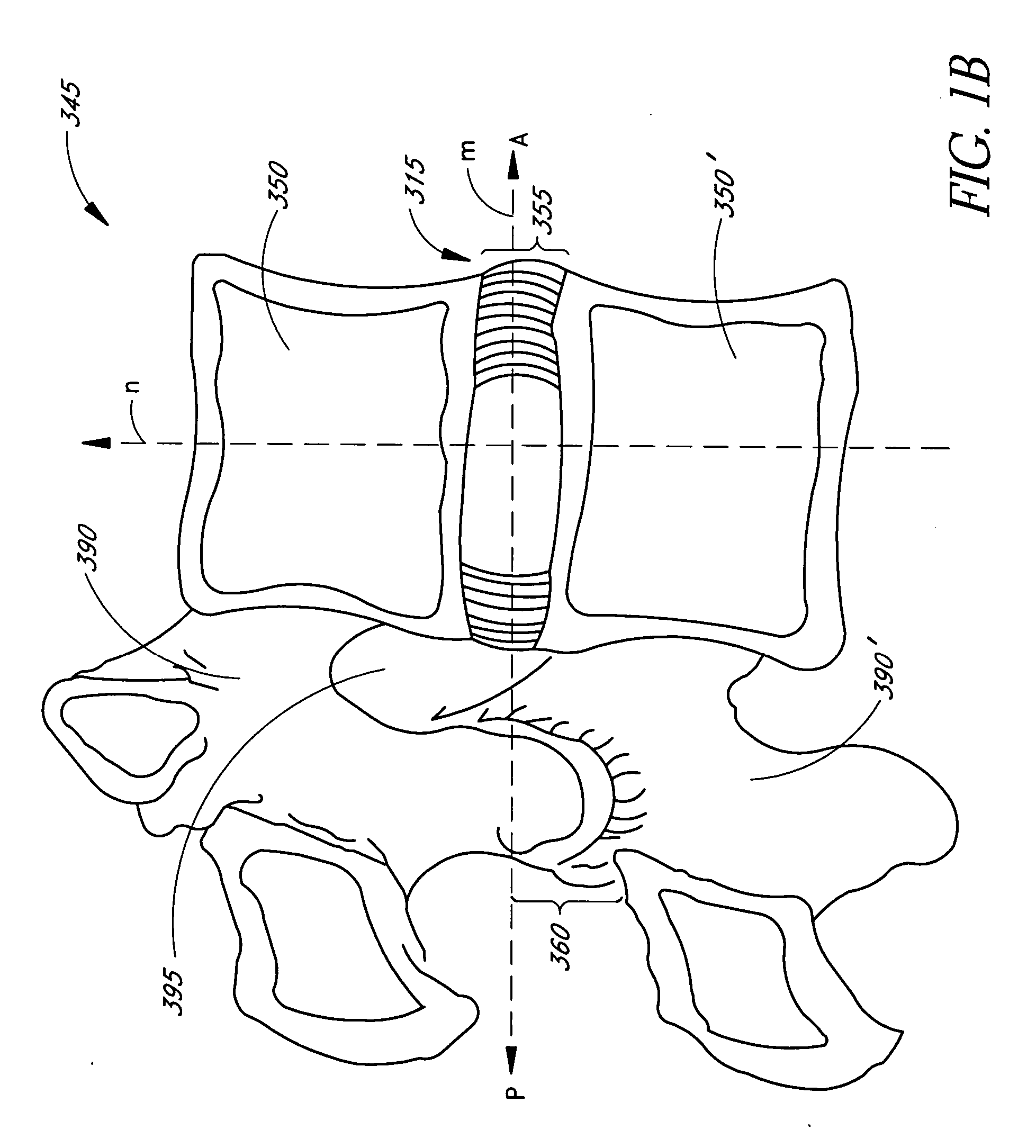
[0028]FIGS. 1A and 1B show the general anatomy of a functional spine unit. In this description and the following claims, the terms ‘anterior’ and ‘posterior’, ‘superior’ and ‘inferior’ are defined by their standard usage in anatomy, e.g., anterior is a direction toward the front (ventral) side of the body or organ, posterior is a direction toward the back (dorsal) side of the body or organ; superior is upward (toward the head) and inferior is lower (toward the feet).

[0029]FIG. 1A is an axial view along the transverse axis M of a vertebral body with the intervertebral disc 315 superior to the vertebral body. Axis M shows the anterior (A) and posterior (P) orientat...


PUM


Abstract

The present invention relates generally to devices and methods for delivering medical devices, such as implants, to desired tissue sites, such as the intervertebral disc. In one aspect, an intervertebral disc repair and diagnostic device that is minimally invasive and that provides precise access to the desired site is provided. In some aspects, the device and method are adapted to deliver, position and expand implants that are initially oriented and compressed for minimally invasive, yet precise and effective implantation.

Description

RELATED APPLICATIONS [0001] This application is a continuation of co-pending U.S. application Ser. No. 10 / 873,074, filed Jun. 21, 2004, and claims priority under 35 U.S.C. §119(e) to U.S. Provisional Appl. No. 60 / 480,276, filed Jun. 20, 2003, herein incorporated by reference.BACKGROUND OF THE INVENTION [0002] 1. Field of the Invention [0003] The present invention relates generally to devices and methods for delivering implants to an intervertebral disc. Specifically, in some embodiments, apparatus and methods for delivering implants that are oriented and compressed for minimally invasive, yet precise and effective implantation are provided. [0004] 2. Description of the Related Art [0005] Various implants, surgical meshes, patches, barriers, tissue scaffolds and the like may be used to treat intervertebral discs and are known in the art. Surgical repair meshes are used throughout the body to treat and repair damaged tissue structures such as intralinguinal hernias, herniated discs an...

Claims


Application Information

Patent Timeline
Patent Type & Authority Applications(United States)
IPC IPC(8): A61B17/88A61B17/70A61B17/72A61F2/44A61F2/46
CPCA61B17/7225A61F2002/4627A61F2002/4435A61F2/4611
Inventor GORENSEK, BOGOMIRLAMBRECHT, GREGORY H.KAVANAUGH, SEANMOORE, ROBERT KEVIN
Owner INTRINSIC THERAPEUTICS
Learn More