
Seat belt arrangement

a seat belt and arrangement technology, applied in the direction of safety belts, pedestrian/occupant safety arrangements, vehicular safety arrangements, etc., can solve the problems of difficult to vary the level of energy absorbed in response, undesirable application of excessive force, and many systems are relatively complex

Active Publication Date: 2006-11-16
AUTOLIV DEV AB
View PDF7 Cites 5 Cited by
  • Summary
  • Abstract
  • Description
  • Claims
  • Application Information

AI Technical Summary

Benefits of technology

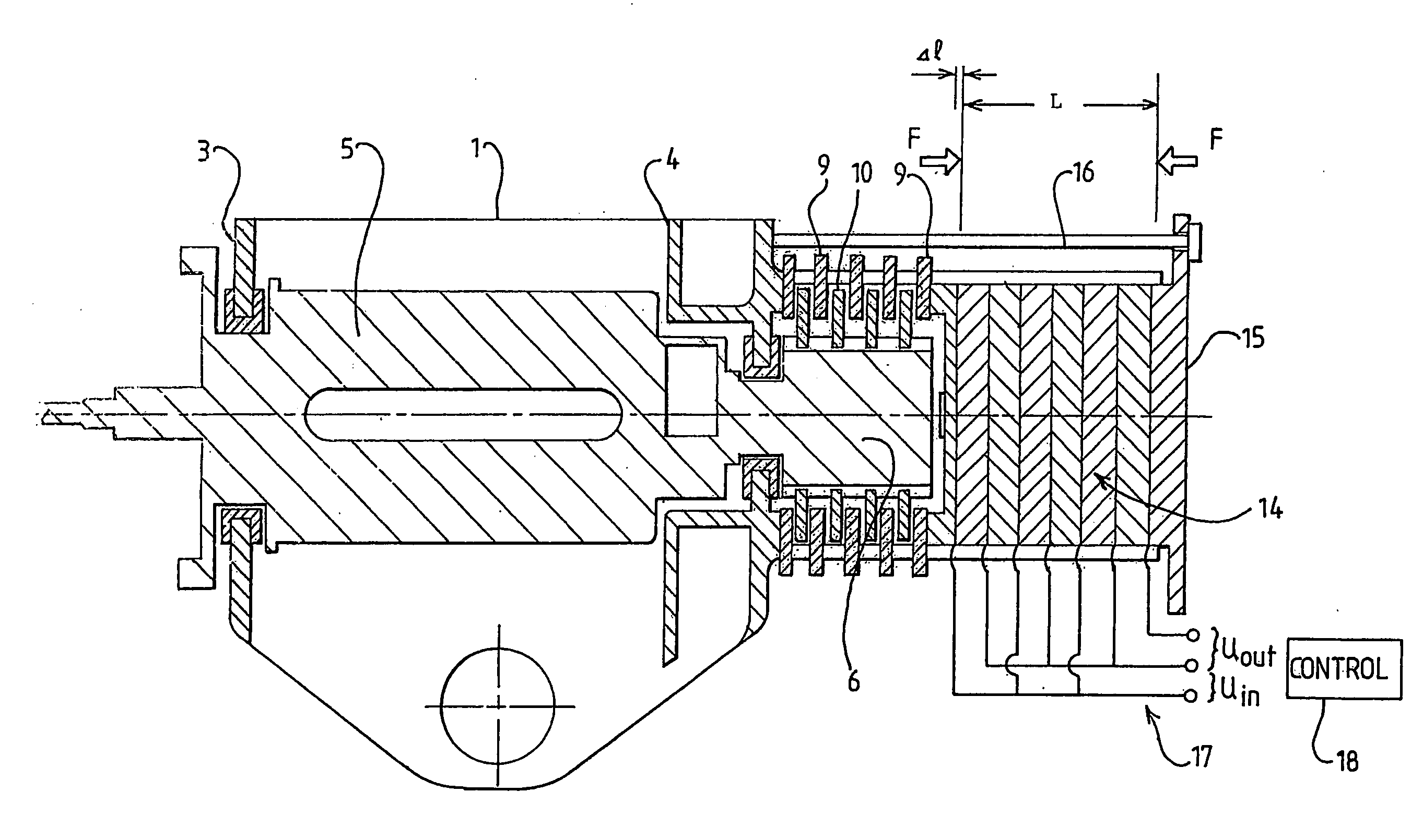
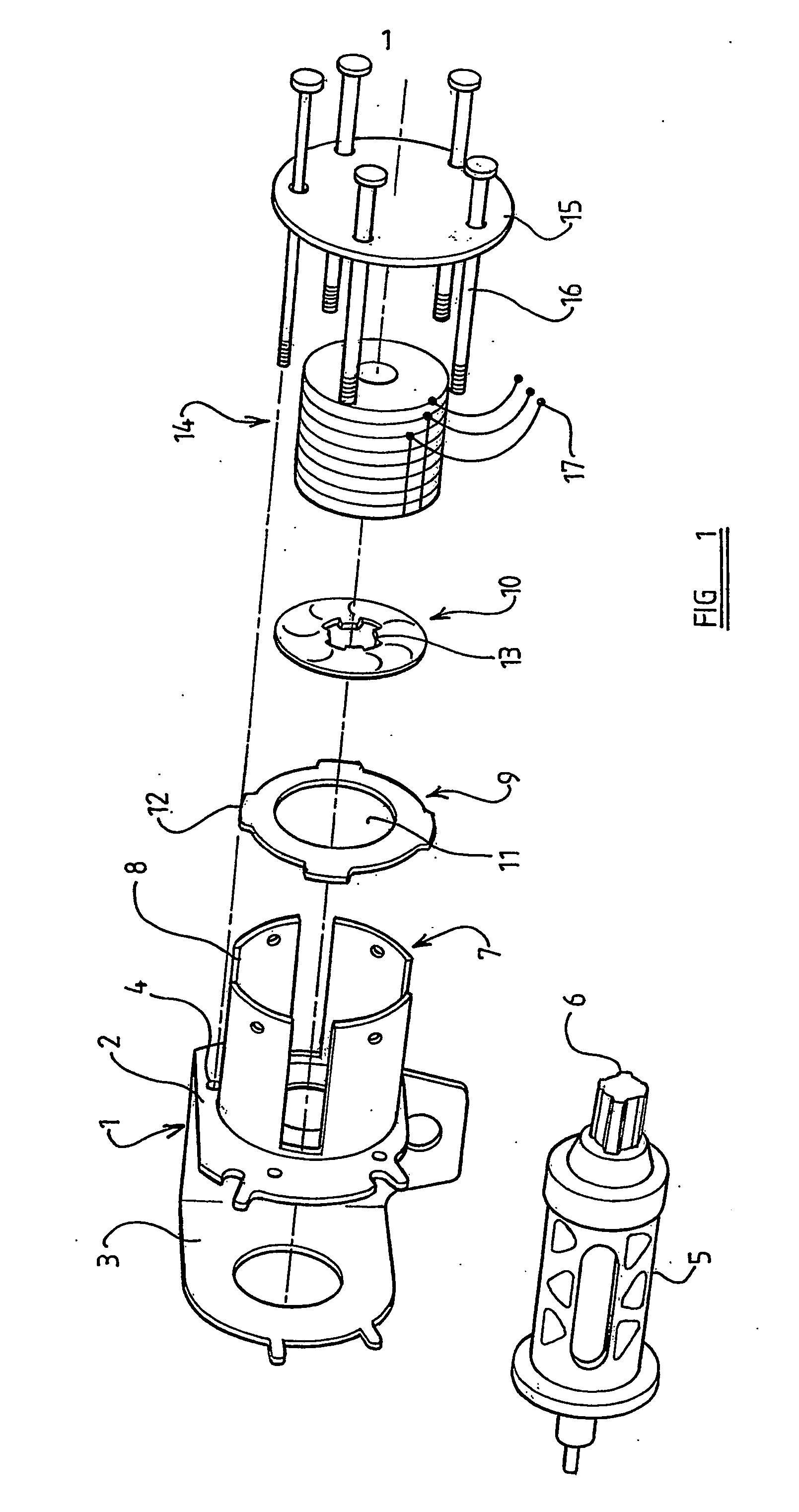
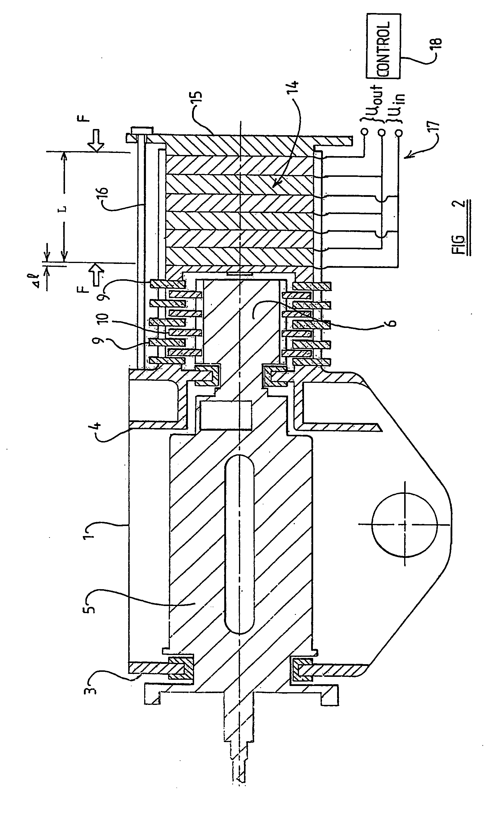
The present invention is an improved seat-belt arrangement with an energy-absorber. The arrangement includes a seat-belt and an energy-absorbing force limiter. The force limiter has two components that move relative to each other when a force is applied. The force applying mechanism is made of electro-deformable material, which can apply a force to the components when an electric potential is applied. The force applying mechanism can include a control arrangement to control the potential applied. The force sensor can measure the actual belt force and the control arrangement can adjust the desired belt force based on the input signals. The force sensor can be placed in the belt anchorage or the seat occupant position sensors can be used. The motion between the components can be either angular or linear. The force limiter can be connected to the seat-belt or the vehicle's anchoring point. The technical effect of this invention is to provide a safer and more effective seat-belt arrangement with improved energy absorption.

Problems solved by technology

Whilst it is always desirable to ensure that an occupant of a vehicle should not accelerate or decelerate substantially with reference to the vehicle during an accident situation, it is known that it is undesirable to apply excessive forces to the torso of an occupant through a seat-belt in order to achieve this objective, since the application of high forces may injure the occupant of the vehicle.
Such arrangements are relatively simple and have a very predictable operating characteristic, but suffer from the disadvantage that it is not easy to vary the level of energy absorbed in response, for example, to the weight of the occupant of the seat or the position of the occupant of the seat immediately before commencement of the accident.
The energy absorbed by a force limiter as used in the context of a safety-belt in a motor vehicle is rather high, and thus many systems are relatively complex.

Method used


Image

  • Seat belt arrangement
  • Seat belt arrangement
  • Seat belt arrangement

Examples


Embodiment Construction

[0030] In embodiments of the invention friction is used to absorb energy in a force limiter. It has been thought inappropriate to use friction to absorb energy in a force limiter since it is difficult to predict the force-resistive, or energy-absorbing, effect provided by friction, especially in connection with an item of apparatus which remains un-used for a long period of time, whilst suffering environmental changes such as temperature, pressure and humidity changes. Here it is to be understood that typically a force limiter does not operate unless the vehicle in which the force limiter is mounted is involved in a major accident. In many prior proposed force limiters, once the force limiter has operated, it is necessary for the force limiter to be replaced. Thus the force limiter remains mounted in a motor vehicle, often remaining unused for several years, but must be capable of operating in the desired manner at precisely the right moment whenever an accident occurs, providing ex...


PUM


Abstract

A seat-belt arrangement including an energy-absorbing force limiter. A first component, for example in the form of a retractor reel spool is movable relative to a second component, for example the frame-work of the retractor. The spool carries with it elements presenting friction faces which co-operate with further elements carried by the frame. A stack of Piezo-electric elements apply a compressional force driving together the elements having the friction faces to provide a controlled frictional energy-absorbing effect.

Description

CROSS REFERENCE TO RELATED APPLICATION [0001] This application claims priority to GB 0205793.3 filed Mar. 12, 2002 and PCT / SE03 / 00408 filed Mar. 12, 2003. BACKGROUND OF THE INVENTION [0002] The present invention relates to a seat-belt arrangement incorporating a seat-belt and a force limiter. [0003] It has been proposed to use force limiters, and in particular energy-absorbing force limiters, in connection with safety devices provided in motor vehicles such as, for example, seat-belts. The function of a force limiter is to yield, whilst absorbing energy, if the force limiter is subjected to a force in excess of a predetermined threshold. Whilst it is always desirable to ensure that an occupant of a vehicle should not accelerate or decelerate substantially with reference to the vehicle during an accident situation, it is known that it is undesirable to apply excessive forces to the torso of an occupant through a seat-belt in order to achieve this objective, since the application of h...

Claims


Application Information

Patent Timeline
Patent Type & Authority Applications(United States)
IPC IPC(8): B60R22/28B65H75/48B60R22/00B60R21/01B60R21/015B60R22/34
CPCB60R22/28B60R22/3413B60R2022/285B60R21/01544B60R21/01516B60R21/01558B60R2022/288
Inventor ANDES
Owner AUTOLIV DEV AB
Learn More