Vehicle brake hydraulic pressure control apparatus

a hydraulic pressure control and brake technology, applied in the direction of brake systems, etc., can solve the problem that the current value corresponding to the actual differential pressure cannot be correctly obtained, and achieve the effect of stable and gentle pressure-increasing control

Inactive Publication Date: 2006-11-16
ADVICS CO LTD
View PDF6 Cites 22 Cited by
  • Summary
  • Abstract
  • Description
  • Claims
  • Application Information

AI Technical Summary

Benefits of technology

[0036] In this case, the first energizing current value at the point of starting the linear pressure-increasing control becomes smaller than the current-value-corresponding-to-actual-differential-pressure at the same point even if either one of the “slow braking” and “sudden braking” is applied. Accordingly, not only in case where the “sudden braking” is applied but also in case where the “sudden braking” is applied, the wheel cylinder hydraulic pressure can immediately increase after the point of starting the linear pressure-increasing valve. In other words, the occurrence of the “delay in the start of pressure increase of the wheel cylinder hydraulic pressure” when the “slow braking” is applied can be prevented.
[0038] This means that the average increasing slope of the wheel cylinder hydraulic pressure during the linear pressure-increasing control in the predetermined-numberth-time ABS control becomes small in case where the “sudden braking” is applied, compared to the case where the holding control is not executed (e.g., see the period from time t2 to time t3′ in FIG. 14). In other words, the “rapid increase of the wheel cylinder hydraulic pressure over a relatively long period” in case where the “sudden braking” is applied can be prevented.
[0044] The first energizing current value provided to the linear solenoid valve, which is the pressure-increasing valve, can be changed with a simple pattern from the basic pattern, whereby the holding control can be executed during the execution of the linear pressure-increasing control in the predetermined-numberth-time ABS control.
[0046] With this configuration, the pressure-increasing control and the holding control are alternately and periodically executed during the execution of the pressure-increasing control in the predetermined-numberth-time ABS control. Accordingly, the average increasing slope of the wheel cylinder hydraulic pressure during the linear pressure-increasing control in the predetermined-numberth-time ABS control can be made more uniform over the linear pressure-increasing control. As a result, more stable and gentle pressure-increasing control can be achieved during the predetermined-numberth-time ABS control.
[0050] On the other hand, as the increasing slope of the wheel cylinder hydraulic pressure during the (linear) pressure-increasing control in the ABS control increases, the degree of the increase in the slip amount for the “wheel to which the ABS control is to be performed” during the pressure-increasing control increases, in general. In other words, the value indicating the degree of the increase in the slip amount for the wheel during the linear pressure-increasing control in the ABS control can be the value precisely indicating the increasing slope of the wheel cylinder hydraulic pressure.
[0051] From the above, the configuration in which the length of the predetermined period in which each of the periodically executed holding controls is executed is changed in accordance with the value indicating the degree of the increase in the slip amount for the wheel makes it possible to match the increasing slope of the wheel cylinder hydraulic pressure with the predetermined optimum value (or to make the increasing slope of the wheel cylinder hydraulic pressure close to the predetermined optimum value) by prolonging the predetermined period, in case, for example, the degree of the increase in the slip amount for the wheel is great (i.e., in case where the increasing slope of the wheel cylinder hydraulic pressure is great). Consequently, the optimum linear pressure-increasing control based upon the optimum increasing slope of the wheel cylinder hydraulic pressure can be executed during the predetermined-numberth-time ABS control.

Problems solved by technology

In general, the current-value-corresponding-to-actual-differential-pressure cannot correctly be obtained at the point of starting the linear pressure-increasing control in the first-time ABS control.

Method used


Image

  • Vehicle brake hydraulic pressure control apparatus
  • Vehicle brake hydraulic pressure control apparatus
  • Vehicle brake hydraulic pressure control apparatus

Examples


Embodiment Construction

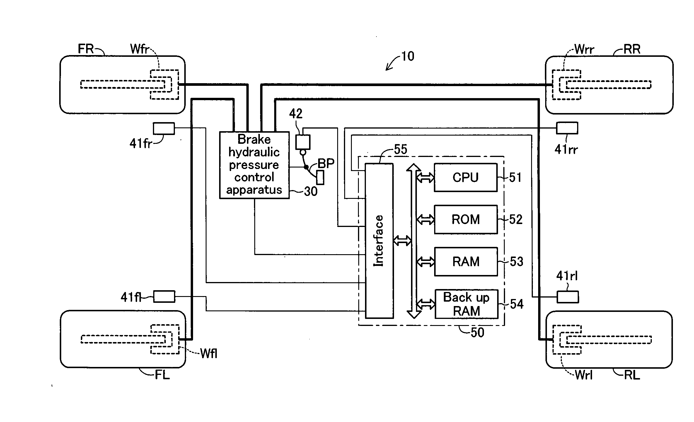
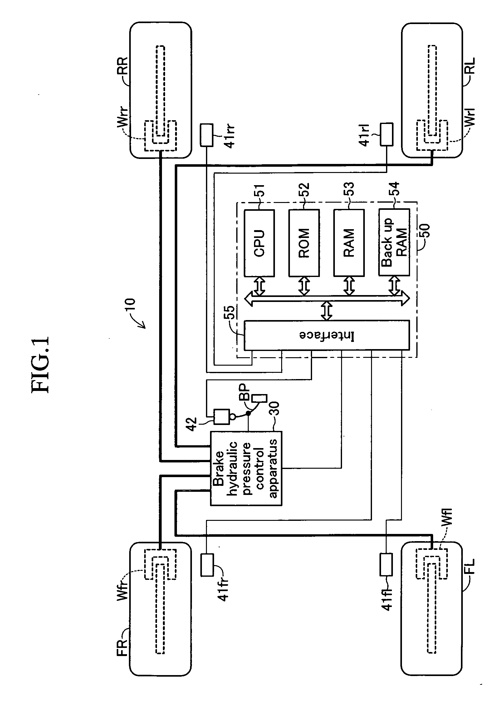
[0067] An embodiment of the present invention will be described with reference to the drawings. FIG. 1 schematically shows the structure of a vehicle equipped with a vehicle motion control apparatus 10 including a brake hydraulic pressure control apparatus according to the present embodiment. The illustrated vehicle is a four-wheel, rear-wheel drive (FR) vehicle having two front wheels (a front left wheel FL and a front right wheel FR), which are non-drive wheels (follower wheels), and two rear wheels (a rear left wheel RL and a rear right wheel RR), which are drive wheels.

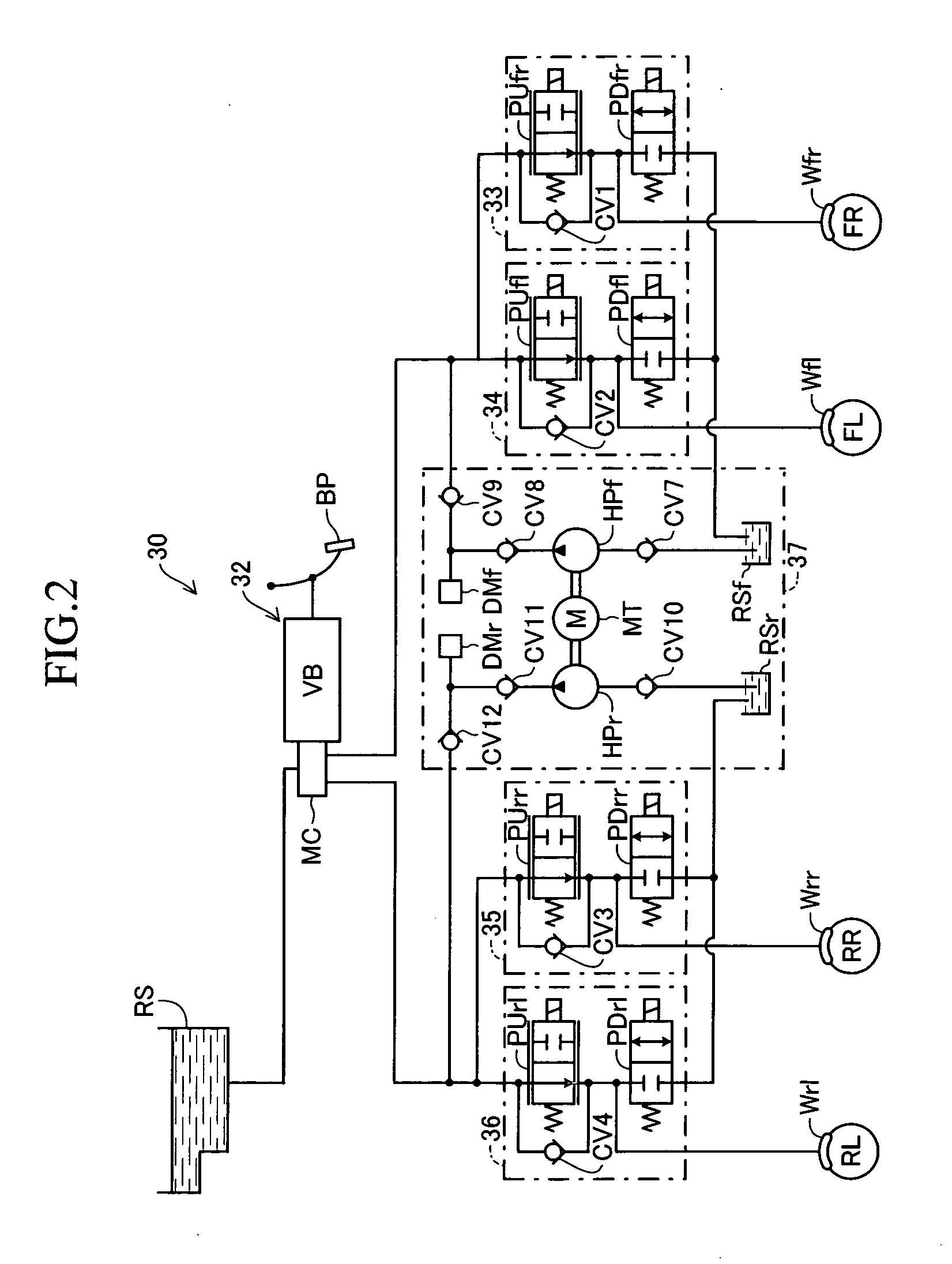
[0068] This vehicle motion control apparatus 10 includes a brake hydraulic pressure control section 30 for generating braking force in each wheel by means of brake hydraulic pressure. As schematically shown in FIG. 2, the brake hydraulic pressure control section 30 includes a brake hydraulic pressure generating section 32 which generates brake hydraulic pressure corresponding to the operating force of a brake ped...


PUM


Abstract

The brake hydraulic pressure control apparatus employs, as a pressure-increasing valve, a normally-open linear solenoid valve that can linearly adjust an actual differential pressure (a difference between a master cylinder hydraulic pressure Pm and a wheel cylinder hydraulic pressure Pw). This apparatus repeatedly executes, in principle, a control cycle in which a pressure-reducing control, holding control and linear pressure-increasing control make one set, while a “linear pressure-increasing control with holding period” is executed instead of the linear pressure-increasing control only in the first-time control cycle that is started in a state where a current-value-corresponding-to-actual-differential-pressure cannot correctly be obtained (the period from time t3 to time t6). The command current value Id (=I0) to the pressure-increasing valve at the point of starting the “linear pressure-increasing control with holding period” is set to a “current-value-corresponding-to-reduced-pressure” that is always smaller than the current-value-corresponding-to-actual-differential-pressure at the same point.

Description

BACKGROUND OF THE INVENTION [0001] 1. Field of the Invention: [0002] The present invention relates to a vehicle hydraulic pressure control apparatus that executes an anti-skid control (hereinafter referred to as “ABS control”) for preventing an excessive slip of a wheel. [0003] 2. Description of the Related Art: [0004] Heretofore, a brake hydraulic pressure control apparatus that controls a brake hydraulic pressure in a wheel cylinder (hereinafter referred to as “wheel cylinder hydraulic pressure”) to execute the ABS control has widely been mounted on vehicles. In general, the brake hydraulic pressure control apparatus is provided with a normally-open solenoid valve (pressure-increasing valve) disposed in a hydraulic circuit between a master cylinder generating a brake hydraulic pressure (hereinafter referred to as “master cylinder hydraulic pressure”) according to a brake operation by a driver and the wheel cylinder and a normally-closed solenoid valve (pressure-reducing valve) dis...

Claims


Application Information

Patent Timeline
Patent Type & Authority Applications(United States)
IPC IPC(8): B60T8/60
CPCB60T8/17616B60T8/445B60T8/4275B60T8/3655
Inventor OBAI, KATSUO
Owner ADVICS CO LTD
Why Eureka
Try Eureka