Double side image scanner

a scanning scanner and side scanner technology, applied in the field of double side scanning scanners, can solve the problems of difficult shortening the scanning time, imposing a significant restriction on the responsiveness of the image sensor, and high time-consuming and cumbersome use, and achieves the effect of enhancing scanning accuracy and reliability, and increasing image quality

Active Publication Date: 2006-11-16
WISECUBE
View PDF11 Cites 16 Cited by
  • Summary
  • Abstract
  • Description
  • Claims
  • Application Information

AI Technical Summary

Benefits of technology

[0010] Taking into account the above and other problems inherent in the prior art, it is an object of the present invention to provide a double side image scanner capable of simultaneously scanning images from opposite surfaces of a medium in an increased image quality and with enhanced scanning accuracy and reliability.

Problems solved by technology

However, the conventional image scanners are designed to sequentially scan one and the other surfaces of a medium one by one, which is highly time-consuming and cumbersome-to-use.
In particular, the speed at which an image sensor or a medium is loaded imposes a significant restriction on the responsiveness of the image sensor.
In other words, it is very difficult to shorten the scanning time due to the design constraint that the loading speed should be inversely proportional to the resolution of the image sensor in order to obtain image data of increased accuracy.
This leads to unrestrained movement and reduced friction, namely, slipping, of the magnetic cards, which may cause a problem of jitter.
Moreover, what is called a spacing loss is created between the magnetic cards and the magnetic stripe reader, which may give rise to an error in reading out the data stored in the magnetic cards.
The size deviation poses a problem in that the magnetic stripe reader may suffer from a tracking error when tracking the magnetic stripe.
Thus, the image scanners have no ability to control the unrestrained movement of the magnetic cards and to compensate the size deviation of the magnetic cards.
As a result, a loading error may be incurred that the magnetic cards are not loaded rectilinearly but turned in a loading process.
In addition, severe distortion appears in the image acquired and the magnetic cards are often jammed when loaded.

Method used


Image

  • Double side image scanner
  • Double side image scanner
  • Double side image scanner

Examples


Embodiment Construction

[0037] Preferred embodiments of a double side image scanner according to the present invention will now be described in detail with reference to the accompanying drawings.

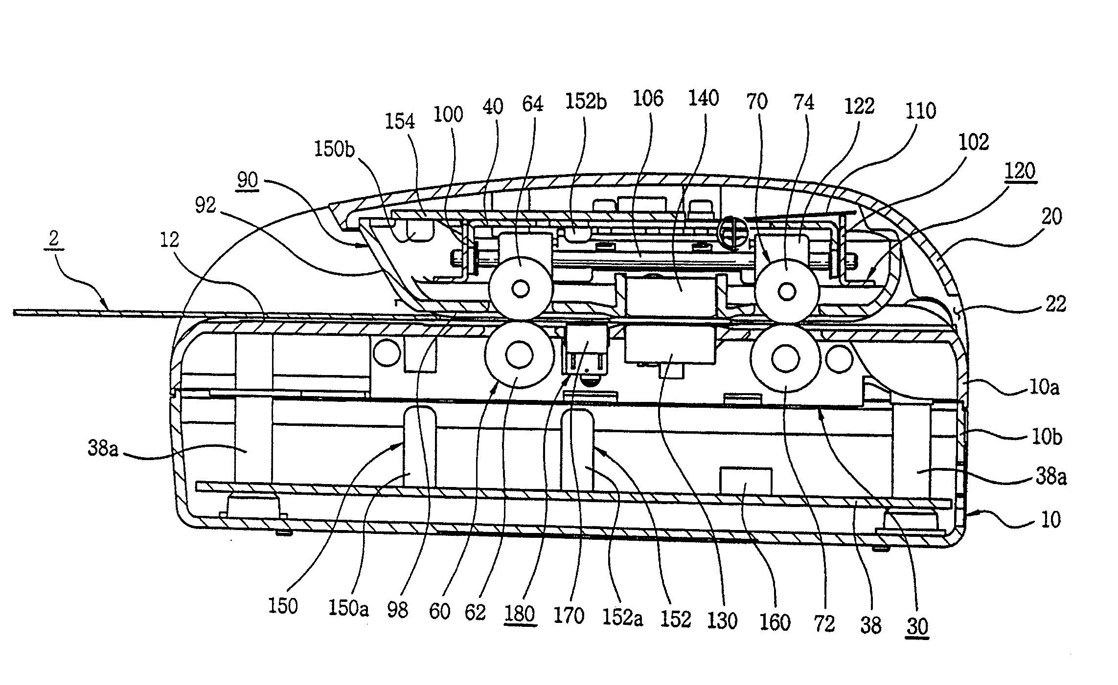
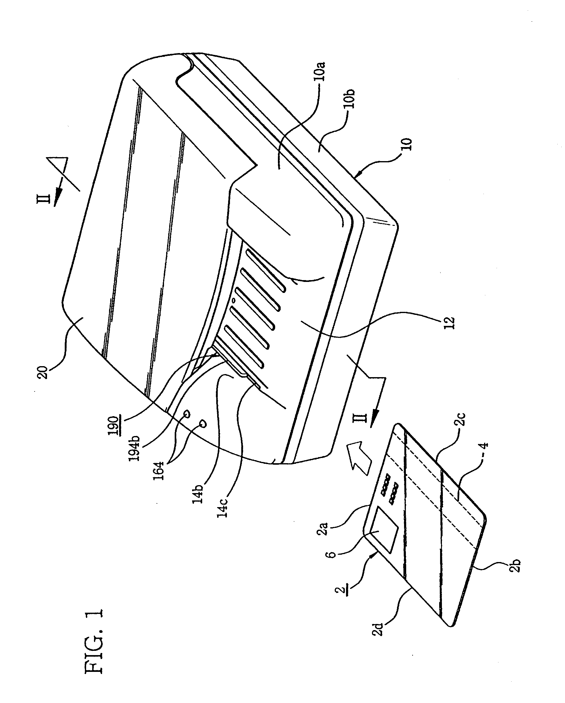
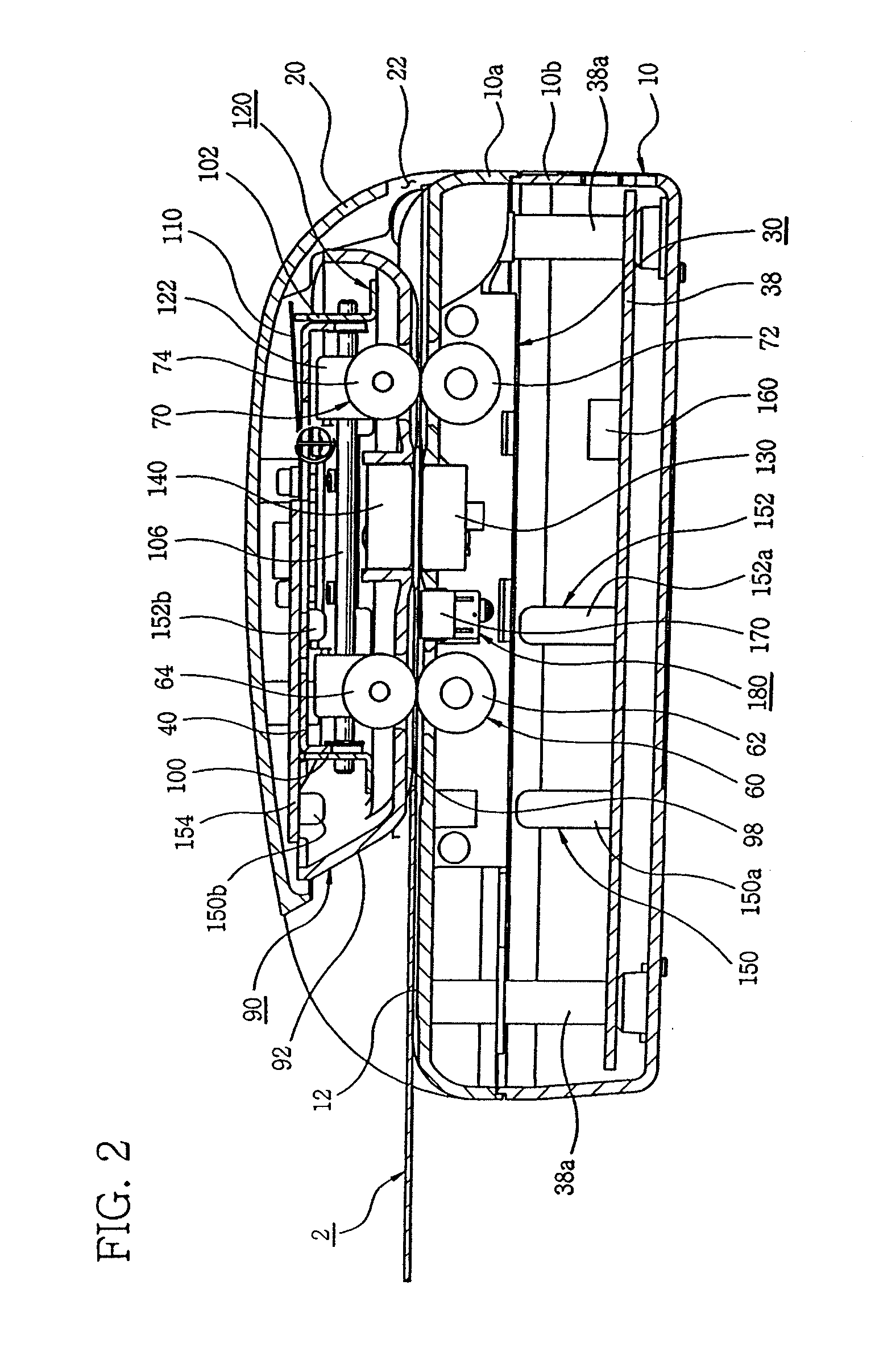
[0038] Referring first to FIGS. 1 through 5, a double side image scanner of the present invention includes a case 10 and a cover 20, both of which cooperate to form a shell of the double side image scanner. The cover 20 is openably attached to the top portion of the case 10. The case 10 is comprised of a top half part 10a and a bottom half part 10b. On the top center area of the case 10, there is provided a guide track 12 for guiding the loading movement of a medium 2 having a size, e.g., similar to that of a magnetic card or an identification card. The medium 2 is loaded and unloaded from the front side of the case 10 through the guide track 12. In FIGS. 1, 4, 13 and 14, there is illustrated a magnetic card, as one example of the medium 2, on one surface of which a magnetic stripe 4 attached. The medium 2 is of a...


PUM


Abstract

A double side image scanner includes a case having a medium guide track with a reference loading line, a main frame mounted inside the case, a first roll feed including a first feed roller mounted on a front side of the guide track and a first idle roller disposed above the first feed roller for cooperating with the first feed roller to load the medium, a second roll feed including a second feed roller mounted on a rear side of the guide track and a second idle roller disposed above the second feed roller for cooperating with the second feed roller to load the medium, a drive device for rotating the first feed roller and the second feed roller, first and second image sensors for scanning opposite surfaces of the medium to acquire image data, and a tracking device for biasing the medium toward the reference loading line.

Description

RELATED APPLICATIONS [0001] The present application is based on, and claims priority from, Korea Application Number 2005-40418, filed May 14, 2005 and Korean Application Number 2005-109230, filed Nov. 15, 2005, the disclosures of which are hereby incorporated by reference herein in their entirety. FIELD OF THE INVENTION [0002] The present invention is directed to a double side image scanner and, more specifically, to a double side image scanner capable of simultaneously scanning images from opposite surfaces of a medium in an increased image quality. BACKGROUND OF THE INVENTION [0003] A scanner is an image input equipment that optically scans storage media, such as documents, drawings, photos, films and the like, and converts analog signals indicative of the intensity of a light reflected or transmitted to digital signals to thereby input digitized images. When in use, the image scanner is interfaced with a computer. [0004] Conventional image scanners are adapted to scan one surface...

Claims


Application Information

Patent Timeline
Patent Type & Authority Applications(United States)
IPC IPC(8): H04N1/00
CPCH04N1/00326H04N1/121H04N2201/0081H04N1/203H04N1/2032H04N1/123
Inventor EOM, GI-YEONGLAH, JONG-KOOKSUH, CHUNG-YONG
Owner WISECUBE
Why Eureka
Try Eureka