
Board inspection apparatus and method and apparatus for setting inspection logic thereof

a technology of inspection logic and inspection apparatus, applied in the direction of instruments, image analysis, image enhancement, etc., can solve the problems of difficult to predict the type of defects generated, difficult to prepare sufficient samples, and difficult to prepare sufficient teaching data before a new componen

Inactive Publication Date: 2006-11-16
ORMON CORP
View PDF2 Cites 25 Cited by
  • Summary
  • Abstract
  • Description
  • Claims
  • Application Information

AI Technical Summary

Benefits of technology

The invention relates to a method and apparatus for setting inspection logic for a previously processed component. The method involves storing the image of the previously processed component, computing color distribution trend data for the focused region in the image, obtaining the image of the new component, computing color distribution trend data for the focused region in the new component, selecting the previously processed component with similar color distribution trend, reading the image of the selected previously processed component, and generating the inspection logic for the new component using the image of the new component and the image of the read previously processed component as teaching data. The technical effect of the invention is to improve the efficiency and accuracy of inspection logic setting for previously processed components.

Problems solved by technology

However, at the actual production site, it is difficult to prepare a sufficient amount of teaching data before a new component is brought for inspection.
Particularly, for a defective product, it is difficult to predict which kind of defect is generated during production, and there are innumerable variations in defects.
Therefore, it is very difficult to prepare the sufficient number of samples that cover all the defects.
Accordingly, a sufficient amount of teaching data cannot be prepared for a certain time after the new component is brought for inspection, which results in a problem that inspection logic reliability cannot be improved.

Method used


Image

  • Board inspection apparatus and method and apparatus for setting inspection logic thereof
  • Board inspection apparatus and method and apparatus for setting inspection logic thereof
  • Board inspection apparatus and method and apparatus for setting inspection logic thereof

Examples


Embodiment Construction

[0031] Preferred embodiments of the invention will be described below with reference to the accompanying drawings.

[0032] (Configuration of Board Inspection System)

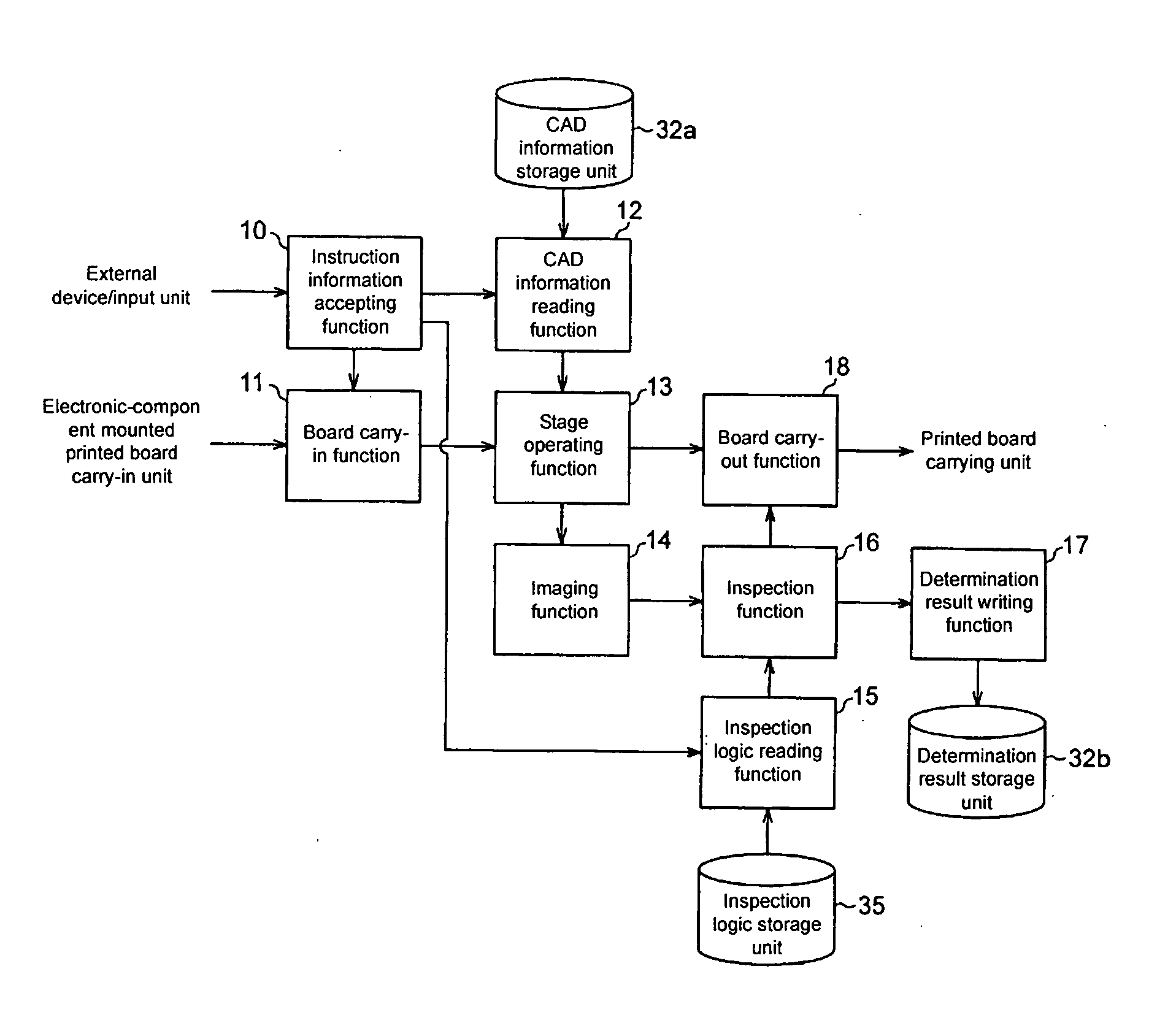
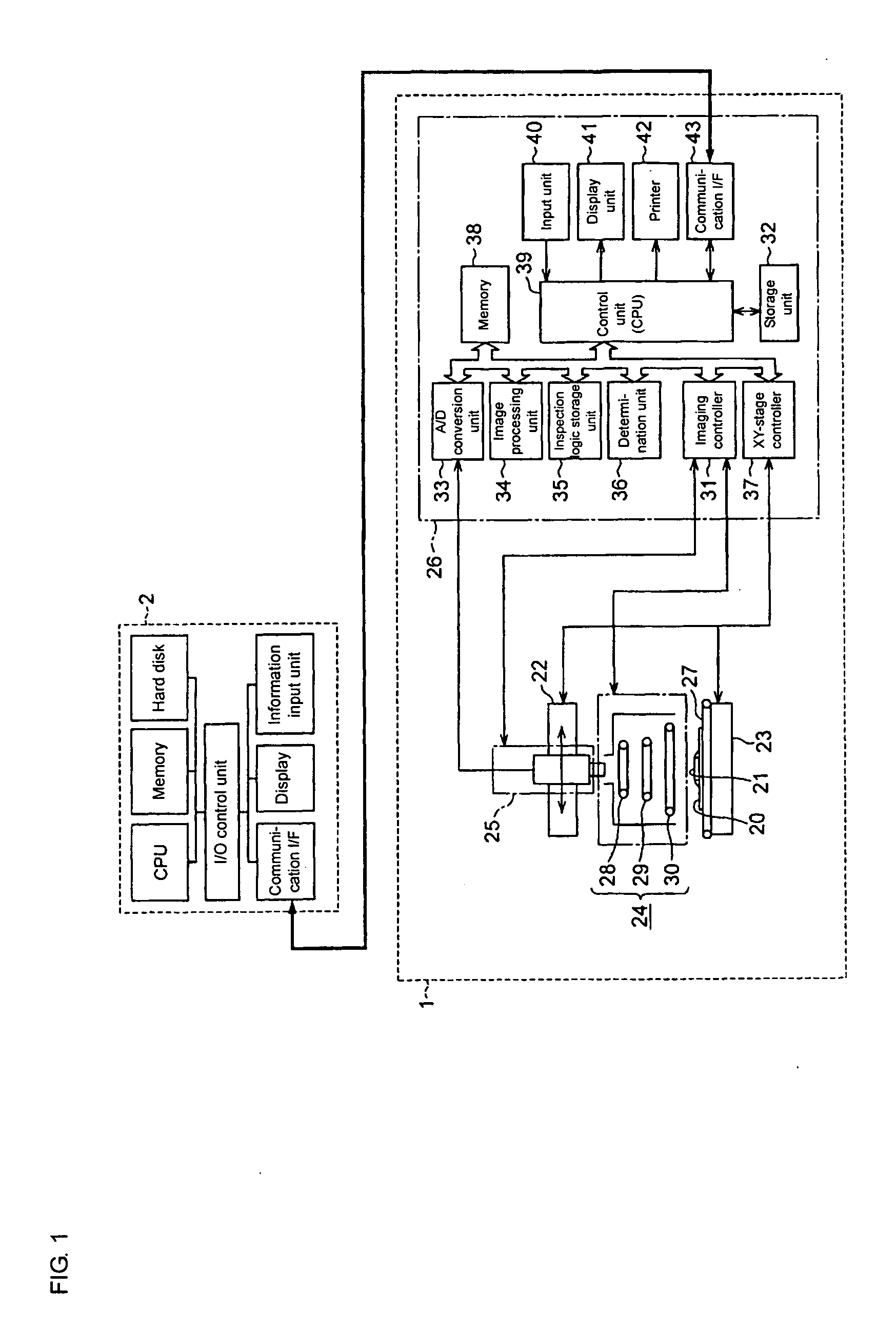
[0033]FIG. 1 shows a hardware configuration of a board inspection system according to an embodiment of the invention.

[0034] The board inspection system includes a board inspection apparatus 1 and an inspection logic setting apparatus 2. The board inspection apparatus 1 perform a board inspection process. The inspection logic setting apparatus 2 automatically generates inspection logic used in the board inspection process of the board inspection apparatus 1. Electronic data such as the image and a parameter can be transferred between the board inspection apparatus 1 and the inspection logic setting apparatus 2 through a wired or wireless network or a storage medium such as MO and DVD. In the embodiment, the board inspection apparatus 1 and the inspection logic setting apparatus 2 are individually formed. However, the boa...


PUM


Abstract

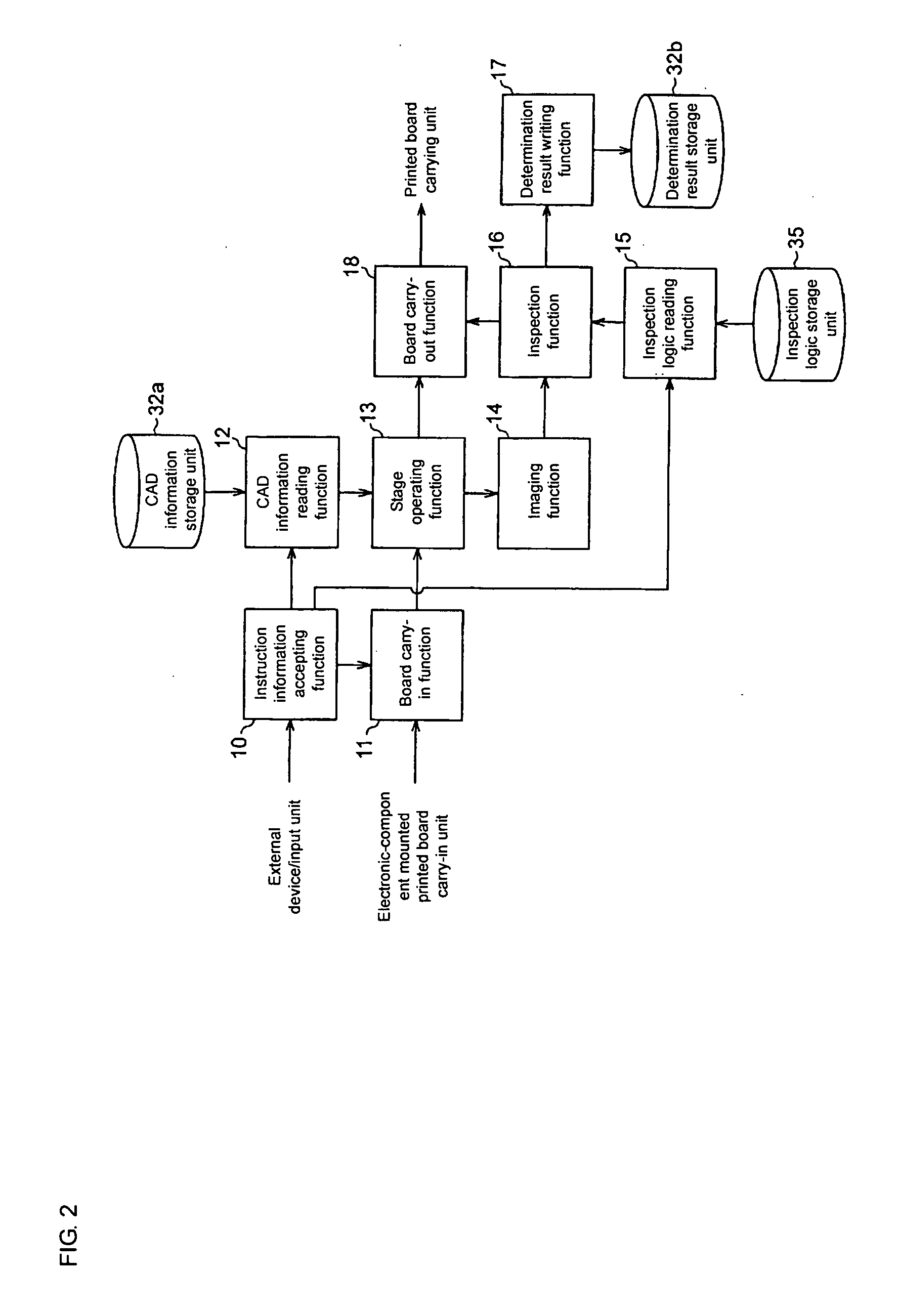
image In generating inspection logic of a new component, the image of a new component is obtained, the trend data for selected characteristics of the focused region of the new component is computed; a previously inspected component having characteristics similar to that of the new component is selected by comparing the trend data of the new component with trend data of the previously inspected component, the image of the selected (previously inspected) component is read from the storage device, and inspection logic for the new component is generated using the images of the new component and images of the previously inspected component as teaching data.

Description

BACKGROUND OF THE RELATED ART [0001] 1. Field of the Invention [0002] The present invention relates to a technology for generating inspection logic used in a board inspection apparatus, particularly to the technology in which the inspection logic can be generated from a small amount of teaching data. [0003] 2. Description of the Related Art [0004] Conventionally, there has been proposed a board inspection apparatus for inspecting surface-mounted quality of a printed board on which many electronic components are mounted, particularly the board inspection apparatus for performing the inspection by using an image in which the board or a part of the printed board is taken. In such pieces of inspection apparatus, it is necessary that inspection logic be previously established to determine whether the surface-mounted quality of the components is acceptable or defective. [0005] Sometimes the following technique is adopted in the inspection apparatus in which the image is utilized. That is,...

Claims


Application Information

Patent Timeline
Patent Type & Authority Applications(United States)
IPC IPC(8): G06K9/00
CPCG06T7/001G06T2207/30152G06T2207/30148G06T2207/30141
Inventor KATAHATA, TAKATOSHIWADA, HIROTAKAMORIYA, TOSHIHIROSHIMIZU, ATSUSHINAKAJIMA, AKIRA
Owner ORMON CORP
Learn More