RFID systems and methods employing infrared localization

a technology of infrared localization and rfid system, which is applied in the direction of burglar alarm mechanical actuation, using reradiation, instruments, etc., can solve the problems of ineffective attempts to identify the tag location based on rf signal strength, high cost, and limited performan

Active Publication Date: 2006-11-23
RF CODE
View PDF83 Cites 69 Cited by
  • Summary
  • Abstract
  • Description
  • Claims
  • Application Information

AI Technical Summary

Problems solved by technology

Therefore, attempting to identify tag location based on RF signal strength has been generally ineffective.
Usable RFID localization systems based upon RF signal time-of-flight have been developed and deployed, however, these systems are complex, expensive, and often of limited performance, particularly indoors, because of reflections and other problems.
However, existing RFID systems employing IR signals have limited localization capabilities.
Moreover, existing RFID systems employing IR signals generally have rigid hardware designs that cannot be adapted for use on multiple applications under programmable processor and system control.

Method used


Image

  • RFID systems and methods employing infrared localization
  • RFID systems and methods employing infrared localization
  • RFID systems and methods employing infrared localization

Examples


Embodiment Construction

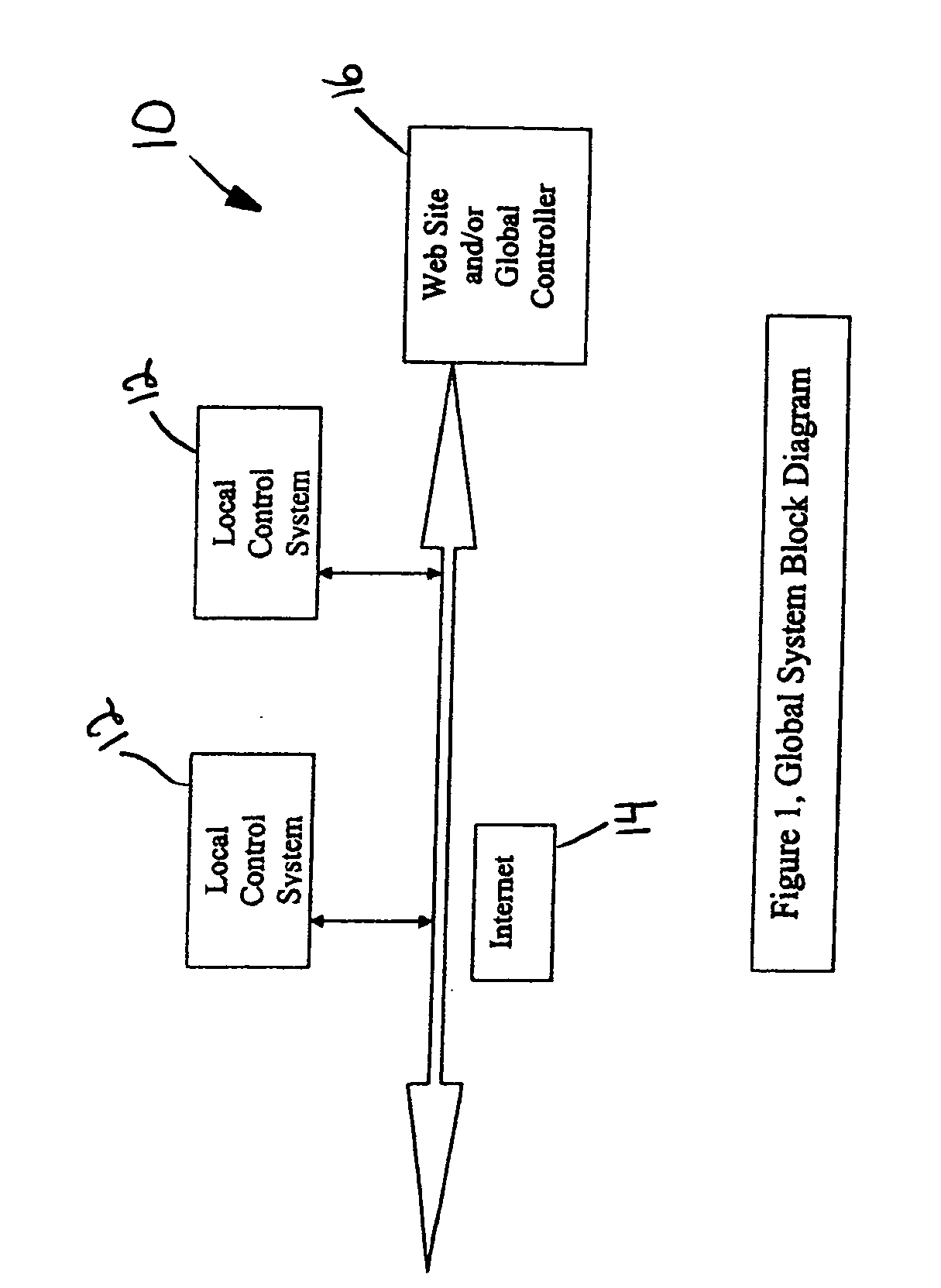
[0022] There is a need for improved IR methods of signal generation as well as IR and RF communication formats. Such improved methods and formats may (1) minimize or prevent collisions between signpost or tag signals, (2) enhance data acquisition to include audio, video and image data, (3) improve localization, (4) provide for the capability to operate a system locally and / or globally over the Internet, by WI-FI, over telephone lines, cables or other means, (5) determine location or position from multiple signposts, (6) utilize signposts having multiple transmitter outputs and signal diversity for improved performance.

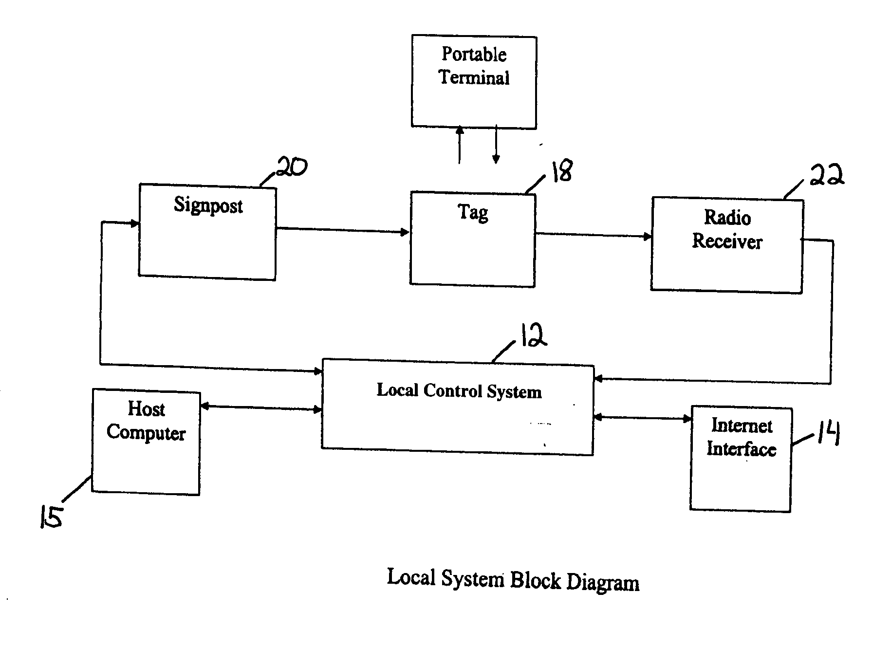
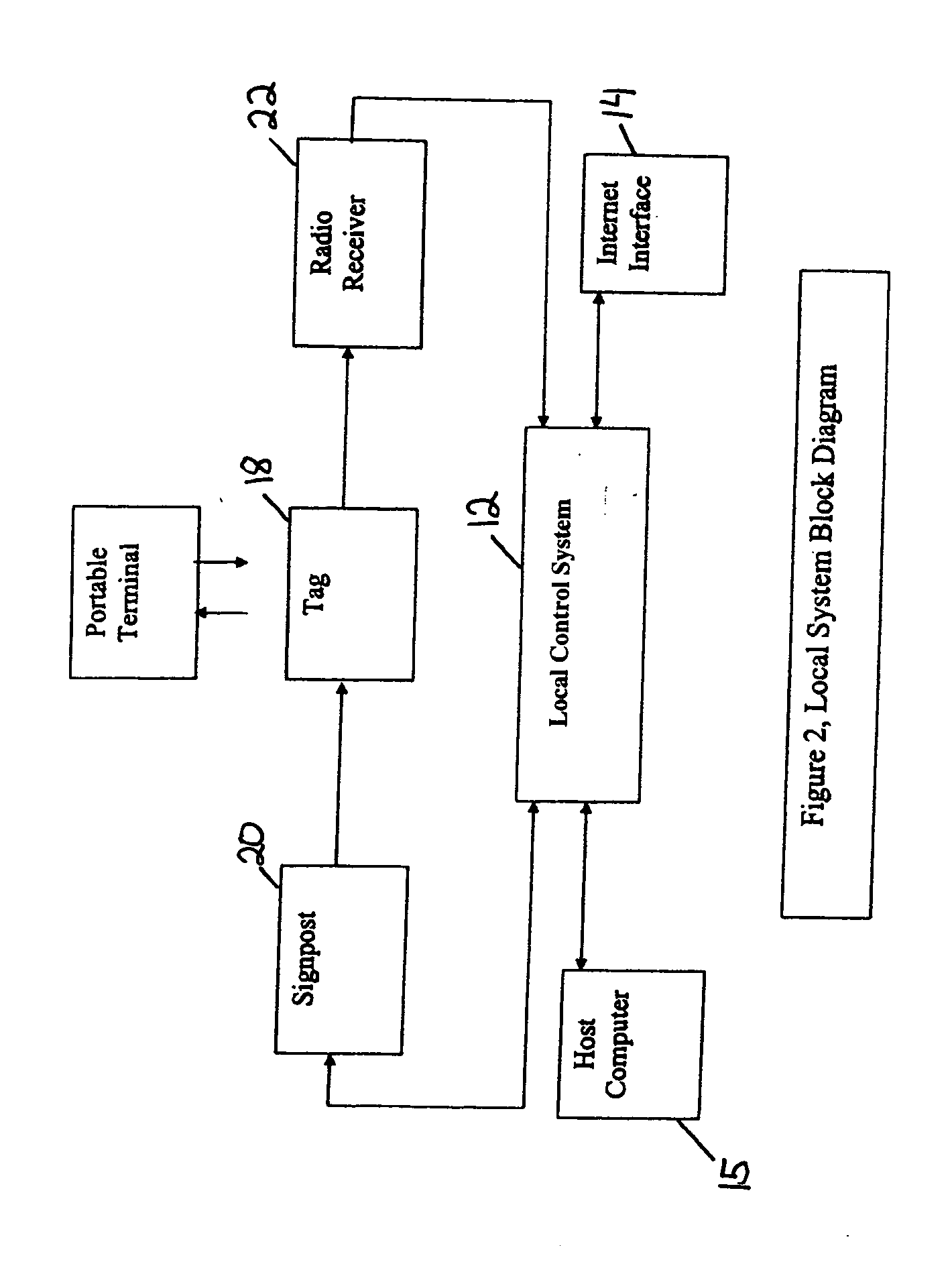
[0023] One aspect of the present invention may include a monitoring system that can operate in an open-loop or one-way fashion, with location, status, data, programs, controls, instructions, or other communication between a signpost to a tag, from the tag to a receiver, and / or from the receiver to a system controller.

[0024] Another aspect of the present invention may...


PUM


Abstract

A series of radio frequency identification (RFID) systems are delineated. One such RFID system comprises an RFID signpost, and a plurality of infrared transmitters, wherein each infrared transmitter of the plurality of infrared transmitters is arranged to cover, when transmitting, a distinct sector relative to the RFID signpost. Another RFID system comprises an RFID signpost having a transmitter for transmitting signals of a predefined type, and a receiver for receiving signals of the predefined type, wherein the transmitter for transmitting signals of the predefined type cannot transmit until a determination is made that the predefined type of signal is not present at the receiver. Still another RFID system comprises an RFID signpost including a transmitter having a continuous power dissipation rating, and a processor for controlling the transmitter such that peak pulse power of a transmission from the transmitter multiplied by its duty cycle does not exceed the continuous power dissipation rating for the transmitter.

Description

CROSS REFERENCE TO RELATED APPLICATION [0001] This application is related to and claims priority from U.S. Appl. No. 60 / 675,280, filed Apr. 26, 2005, in the name of Koerner, et al. and entitled “Radio Frequency Identification Device System with Infrared Localization,” the full content of which is incorporated by reference.FIELD OF THE INVENTION [0002] The present invention relates to radio frequency identification (RFID) systems and methods, and more particularly, to RFID systems and methods employing infrared (IR) localization. BACKGROUND OF THE INVENTION [0003] RFID is an automatic identification method, relying on storing and remotely retrieving data using devices called RFID tags, tags or transponders. An RFID tag is typically a small object that can be attached to or incorporated into an object, animal, or person. RFID tags may contain silicon chips and antennas to enable them to receive and respond to radio-frequency queries from an RFID transceiver. Passive tags require no in...

Claims


Application Information

Patent Timeline
Patent Type & Authority Applications(United States)
IPC IPC(8): G08B13/14
CPCG01S5/16G01S1/70G01S2201/01
Inventor KOERNER, STEVEWORTHY, DAVID
Owner RF CODE
Why Eureka
Try Eureka