Orthodontic bracket base and bracket using the base

a technology for orthodontic brackets and brackets, applied in dental tools, dental surgery, medical science, etc., can solve the problems of serious damage to the tooth surface, difficulty in separating brackets from the tooth surface, and insufficient consideration of the importance of separation functions

Active Publication Date: 2006-11-23
MOON SEUNG SOO
View PDF4 Cites 11 Cited by
  • Summary
  • Abstract
  • Description
  • Claims
  • Application Information

AI Technical Summary

Benefits of technology

[0016] Another object of the present invention is to provide an orthodontic bracket which is constructed to prevent an insert from being released from a slot.
[0018] Thanks to the features of the bracket base, an excellent characteristic of adhesion of the bracket to the tooth surface is obtained, and the bracket can be easily separated from the tooth surface after orthodontic treatment is finished.
[0021] Thanks to the features of the bracket, in addition to the above-mentioned working effects obtained due to the construction of the bracket base, the insert can be prevented from being released from the slot.

Problems solved by technology

However, in this conventional technique, special emphasis is placed only on improving the adhesive function, and the importance of the separation function is not appropriately considered.
Therefore, a problem occurs in that it is difficult to separate the bracket from the tooth surface to the extent that the adhesion strength of the bracket with respect to the tooth surface is improved.
Further, serious damage to the tooth surface may occur.
Nevertheless, in this conventional technique, special emphasis is placed only on the improvement of the separability of the bracket, and measures for solving the problem caused by the degradation of the adhesive function which results from the improvement of the separation function are not provided.
Even in the type of bracket shown in FIG. 2, a drawback exists in that the insert 4 is likely to be released from its normal installation position due to the movement of a wire fitted into the slot 2a of the insert 4 in the course of performing ligation.

Method used


Image

  • Orthodontic bracket base and bracket using the base
  • Orthodontic bracket base and bracket using the base
  • Orthodontic bracket base and bracket using the base

Examples


Embodiment Construction

[0030] Reference will now be made in greater detail to a preferred embodiment of the invention, an example of which is illustrated in the accompanying drawings. Wherever possible, the same reference numerals will be used throughout the drawings and the description to refer to the same or like parts.

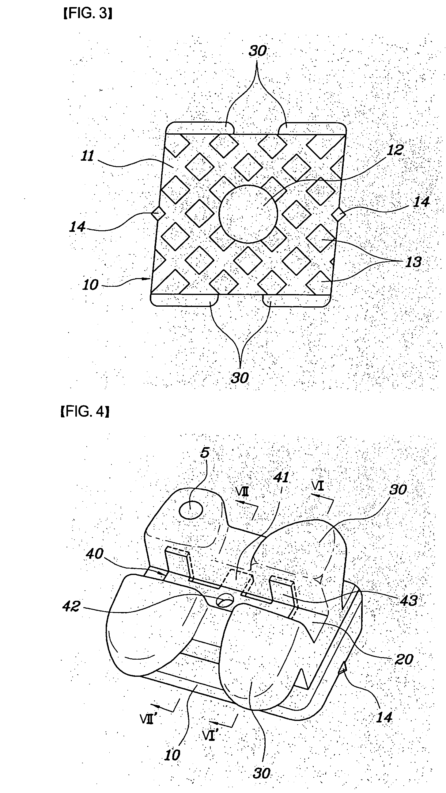
[0031] Referring to FIGS. 3 through 7, a metal-reinforced ceramic bracket is illustrated as an example of a bracket according to the present invention.

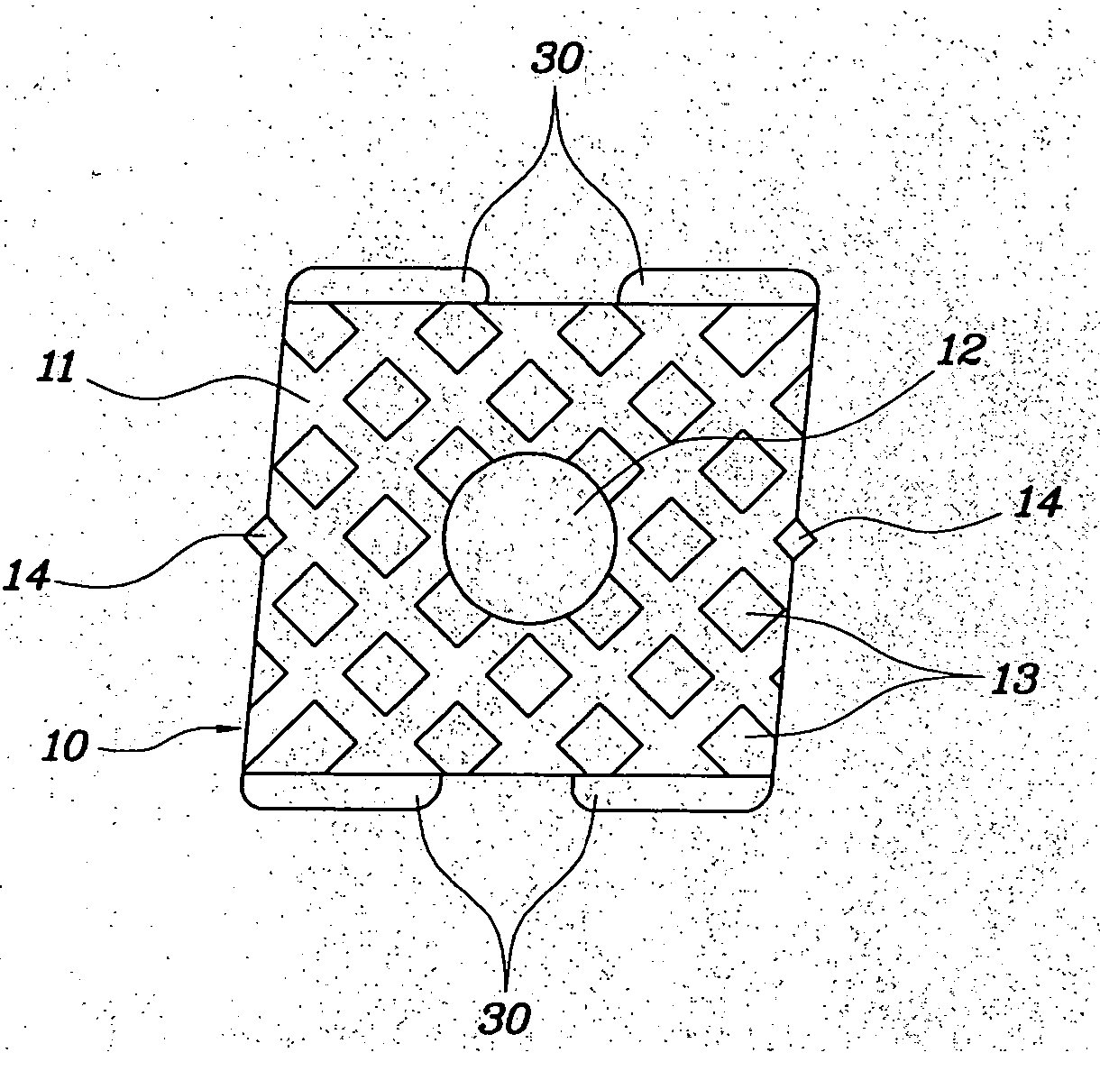
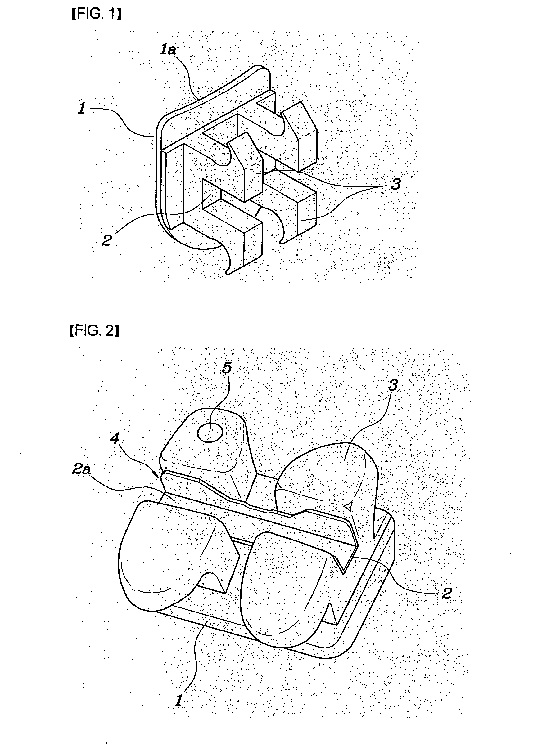
[0032] As shown in FIGS. 3 and 4, the bracket comprises a base 10 secured to a tooth surface, a slot 20 defined on the rear surface of the base 10 to allow a wire (not shown) to be fitted therein, wings 30 arranged at both sides of the slot 20, and an insert 40 installed in the slot 20.

[0033] The base 10 is a member which has a predetermined thickness and a substantially rectangular configuration. The front surface of the base 10 is directly bonded to the tooth surface using an adhesive. On the rear surface of the base 10 are provided me...


PUM


Abstract

Disclosed is an orthodontic bracket which has excellent adhesion to a tooth surface and can be easily separated from the tooth surface after orthodontic treatment is finished. The base of the orthodontic bracket comprises an adhesion surface brought into dose contact with a tooth surface; a central projection located at a center portion of the adhesion surface; and a plurality of surrounding projections arranged at regular intervals around the central projection and made of a material which allows force of adhesion to the tooth surface of an adhesive to be greater at the surrounding projections than at the central projection.

Description

BACKGROUND OF THE INVENTION [0001] 1. Field of the Invention [0002] The present invention relates, in general, to an orthodontic bracket base and an orthodontic bracket having the base, and more particularly, to an orthodontic bracket base which has a characteristic of excellent adhesion to a tooth surface and can be easily separated from the tooth surface after orthodontic treatment is finished, and to an orthodontic bracket having the base. [0003] 2. Description of the Prior Art [0004] As is generally known in the art, the parts used for correcting an irregularly arranged set of teeth mostly include orthodontic brackets (hereinafter, referred to as “brackets”), each of which is secured to a tooth surface, and an arch wire which connects the brackets to one another so as to apply tension force to thereby correct the irregular set of teeth. [0005] Referring to FIG. 1, a metal bracket is illustrated as one example of a conventional bracket. As can be seen from FIG. 1, the bracket com...

Claims


Application Information

Patent Timeline
Patent Type & Authority Applications(United States)
IPC IPC(8): A61C3/00
CPCA61C7/16A61C7/14
Inventor MOON, SEUNG SOO
Owner MOON SEUNG SOO
Why Eureka
Try Eureka