Mammography method and apparatus for forming a tomosynthetic 3-D X-ray image

a tomosynthetic, 3d x-ray technology, applied in mammography, medical science, diagnostics, etc., can solve problems such as affecting detection accuracy, and achieve the effect of increasing descriptiveness

Inactive Publication Date: 2006-11-30
SIEMENS AG
View PDF2 Cites 51 Cited by
  • Summary
  • Abstract
  • Description
  • Claims
  • Application Information

AI Technical Summary

Benefits of technology

[0008] An object of the present invention is to provide a mammography method and a mammography devic...

Problems solved by technology

Since in such a projection the tissue layers lying behind one another in the direction of the X-ray beam are s...

Method used


Image

  • Mammography method and apparatus for forming a tomosynthetic 3-D X-ray image
  • Mammography method and apparatus for forming a tomosynthetic 3-D X-ray image
  • Mammography method and apparatus for forming a tomosynthetic 3-D X-ray image

Examples


Embodiment Construction

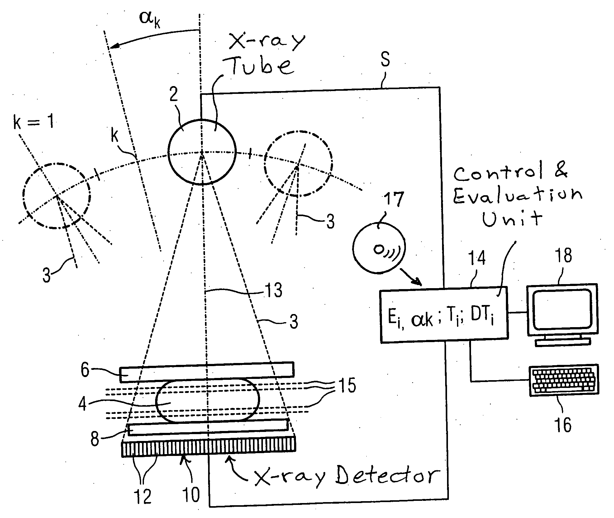
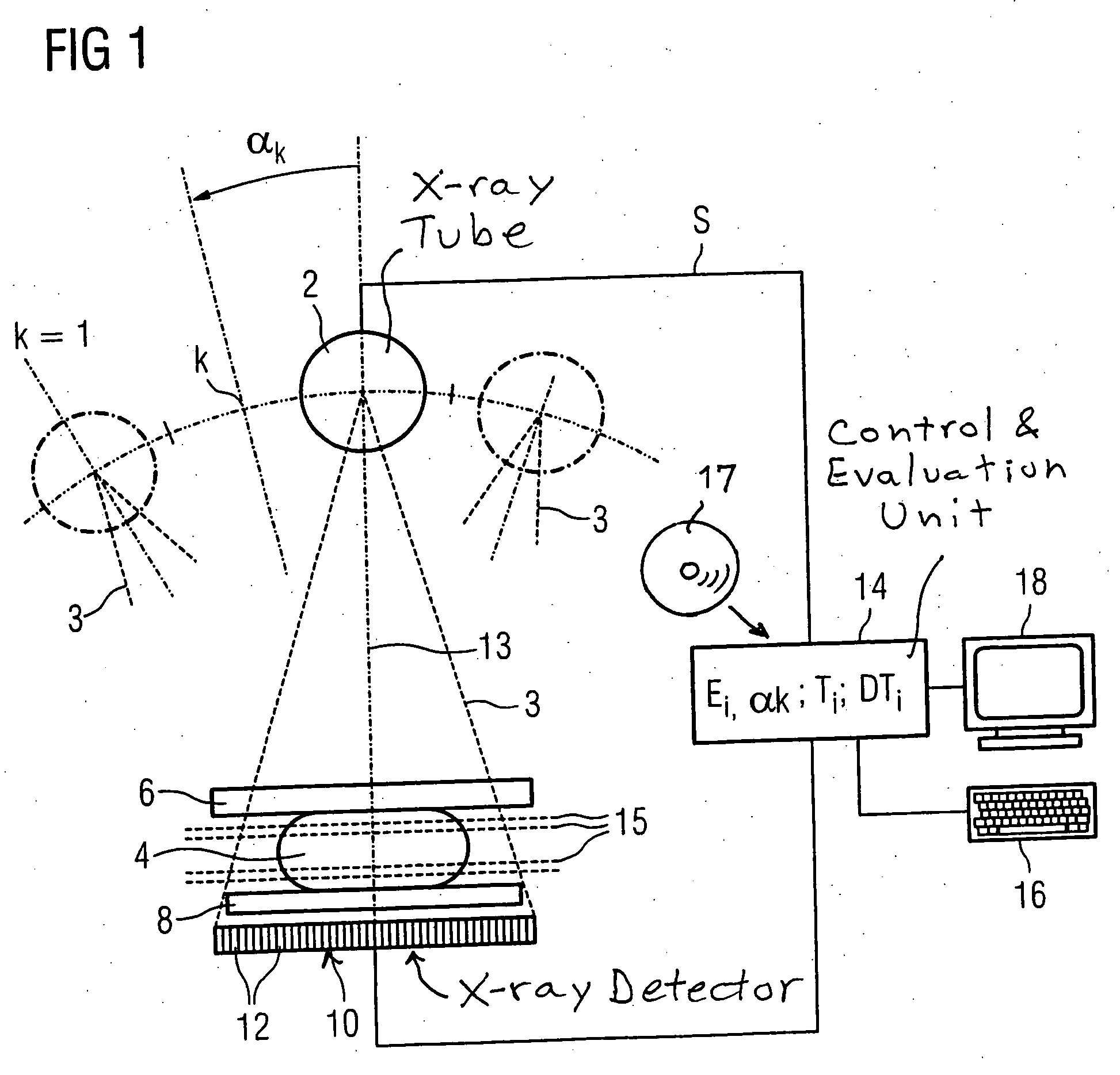
[0022] As shown in FIG. 1, the mammography device has an X-ray tube 2 for the generation of X-rays 3 that penetrate an examination object 4. The examination object 4 is a female breast that is held between a compression plate 6 and a support plate 8. The X-rays 3 penetrating the examination object 4, the compression plate 6, and the support plate 8 are received by a large-surface, particularly an energy-discriminating, digital X-ray detector 10, which is constructed of a number of individual detectors 12 arranged in a matrix-like array. The detector 10 has a detection surface 11 that is parallel to the compression plate 6 and the support plate 8.

[0023] The X-ray tube 2 may be pivoted together with the X-ray detector 10 through different angular positions k=1 . . . n, so that individual images Ei,d,k can be recorded of the examination object 4 at different projection angles αk relative to the normal 13 of the detection surface 11 of the X-ray detector 10. These individual images Ei,...


PUM


Abstract

In a mammography method and a mammography device recorded at different projection angles and a series of second digital individual images recorded at different projection angles are combined into at least one tomosynthetic 3D X-ray image composed of a series of layer images.

Description

BACKGROUND OF THE INVENTION [0001] 1. Field of the Invention [0002] The present invention relates to a mammography method of the type wherein digital individual images recorded in a series at different projection angles are combined into a tomosynthetic 3D X-ray image. Furthermore, the invention relates to a mammography device suitable for performing such a method. [0003] 2. Description of the Prior Art [0004] Mammography is an X-ray examination of the female breast for the purpose of detecting tumors at the earliest possible stage. Continual improvements in the mammography method have as their goal the production of more descriptive X-ray images in order to distinguish between benign and malignant changes and to reduce the number of erroneous findings, that is, the number of suspect findings resulting from non-malignant changes, and the number of malignant tumors not discovered. In conventional X-ray mammography, a two-dimensional image of the compressed breast is produced in a sin...

Claims


Application Information

Patent Timeline
IPC IPC(8): A61B6/04
CPCA61B6/0414A61B6/4241A61B6/502A61B6/482A61B6/466
Inventor MERTELMEIER, THOMAS
Owner SIEMENS AG
Why Eureka
Try Eureka