Interspinous process implant having deployable wings and method of implantation

a technology of process implants and implants, applied in the field of interspinous process implants, can solve the problems of reducing the foraminal area, radicular pain, neck pain and muscle weakness,

Active Publication Date: 2006-11-30
MEDTRONIC EURO SARL
View PDF99 Cites 335 Cited by
  • Summary
  • Abstract
  • Description
  • Claims
  • Application Information

AI Technical Summary

Problems solved by technology

Spinal stenosis results in a reduction foraminal area (i.e., the available space for the passage of nerves and blood vessels) which compresses the cervical nerve roots and causes radicular pain.
Another symptom of spinal

Method used


Image

  • Interspinous process implant having deployable wings and method of implantation
  • Interspinous process implant having deployable wings and method of implantation
  • Interspinous process implant having deployable wings and method of implantation

Examples


Embodiment Construction

Interspinous Implants

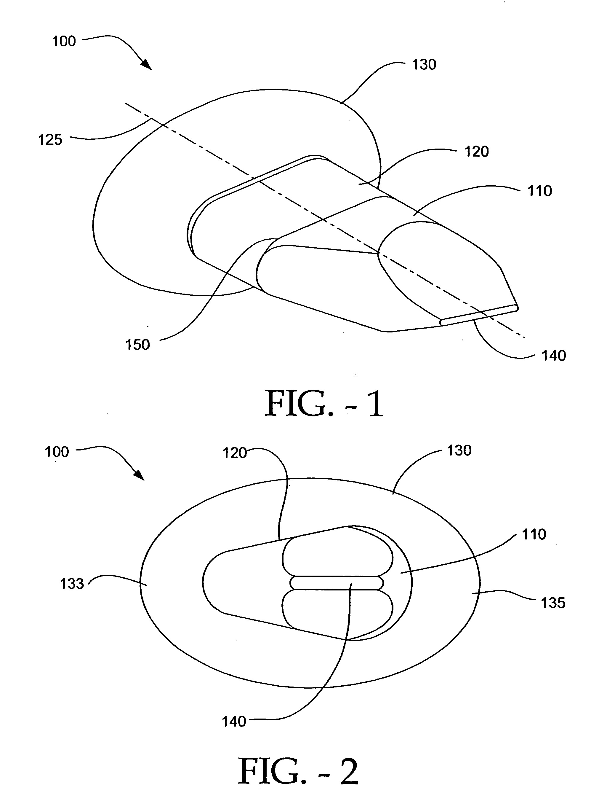
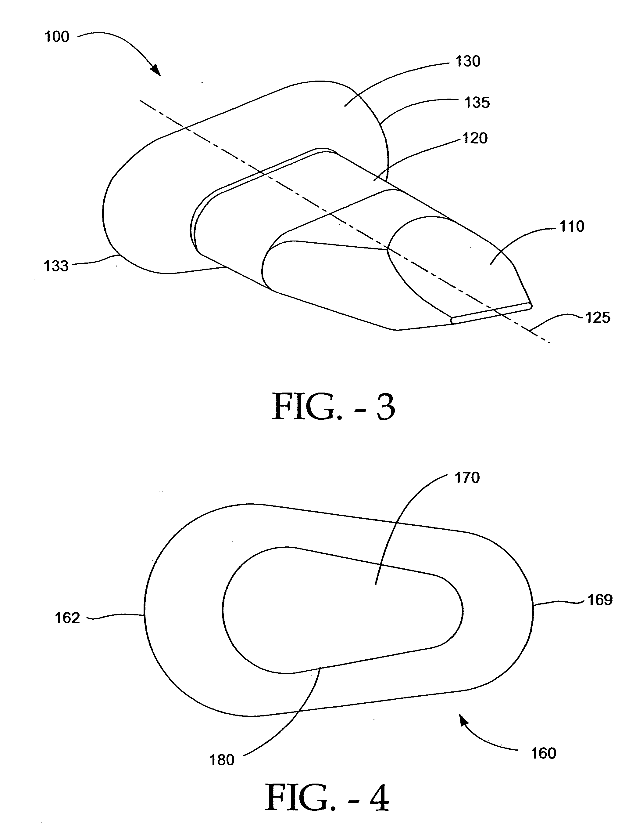
[0056]FIGS. 1 and 2 illustrate an implant 100 in accordance with an embodiment of the present invention. The implant 100 comprises a wing 130, a spacer 120, and a lead-in tissue expander (also referred to herein as a distraction guide) 110. The distraction guide 110 in this particular embodiment is wedge-shaped, i.e., the implant has an expanding cross-section from a distal end of the implant 102 to a region 104 where the guide 110 joins with the spacer 120 (referencing for the figures is based on the point of insertion of the implant between spinous processes). As such, the distraction guide functions to initiate distraction of the soft tissue and the spinous processes when the implant 100 is surgically inserted between the spinous processes. It is to be understood that the distraction guide 110 can be pointed and the like, in order to facilitate insertion of the implant 100 between the spinous processes of adjacent cervical vertebrae. It is advantageous that...


PUM


Abstract

An embodiment of a system in accordance with the present invention can include an implant having a spacer with a thickness and a wing, wherein a first configuration of the wing has a first height substantially similar to the thickness and wherein the wing is adapted to be selectably arranged in a second configuration such that the wing has a second height greater than the first height. A periphery of the implant has a shape generally conformal with a shape of an inner surface of a cannula and a cross-sectional diameter smaller than an inner diameter of the cannula. The cannula is inserted such that a proximal end of the cannula is arranged between the adjacent spinous processes. The implant is then urged into position between the adjacent spinous processes by way of the cannula, and subsequently arranged in a second configuration to fix the implant in position.

Description

CLAIM OF PRIORITY [0001] This application claims benefit to U.S. Provisional Application No. 60 / 672,402 entitled INTERSPINOUS PROCESS IMPLANT HAVING DEPLOYABLE WINGS AND METHOD OF IMPLANTATION, by Zucherman et al., filed Apr. 18, 2005 (Attorney Docket No. KLYC-1096US0), which is incorporated herein by reference. CROSS-REFERENCE TO RELATED APPLICATIONS [0002] This U.S. Patent Application incorporates by reference all of the following co-pending applications and issued patents: [0003] U.S. patent application Ser. No. 10 / 850,267 entitled “Distractible Interspinous Process Implant and Method of Implantation,” by Zucherman et al., filed May 20, 2004 (Attorney Docket No. 1087US2); [0004] U.S. Patent Application No. 60 / 612,465 entitled “Interspinous Process Implant Including a Binder and Method of Implantation,” by Zucherman et al., filed Sep. 20, 2004 (Attorney Docket No. KLYC-01109US0); [0005] U.S. Pat. No. 6,419,676, entitled “Spine Distraction Implant and Method,” issued Jul. 16, 2002 ...

Claims


Application Information

Patent Timeline
IPC IPC(8): A61F2/30
CPCA61B17/7068A61B17/7065A61B17/56A61F2/30A61B17/58
Inventor ZUCHERMAN, JAMES F.HSU, KEN Y.KLYCE, HENRY A.WINSLOW, CHARLES J.YERBY, SCOTT A.FLYNN, JOHN J.MITCHELL, STEVEN T.MARKWART, JOHN A.
Owner MEDTRONIC EURO SARL
Why Eureka
Try Eureka