Automatic rear airfoil for vehicle

a rear airfoil and automatic technology, applied in vehicle body streamlining, monocoque construction, vehicle body, etc., can solve the problems of reducing the drag of the backlight, reducing and reducing the performance of the backlight, so as to reduce the weight of the airfoil, reduce the weight of the backlight, and reduce the weight of the structural reinforcement. , the effect of reducing the weigh

Inactive Publication Date: 2006-12-07
ANDRUS PAUL GUY +1
View PDF3 Cites 49 Cited by
  • Summary
  • Abstract
  • Description
  • Claims
  • Application Information

AI Technical Summary

Problems solved by technology

There are however several practical requirements that pose difficulties to implementing such a device on a working transport trailer.
Given that the device operates in a physically hostile environment, it must not vibrate to a degree that causes premature wear of its structural components.
Boattail surfaces tend to perform aerodynamically better in cross-wind (higher yaw) conditions, however the backlight loses its' drag reducing function as the angle of yaw rises.
A major difficulty in the deployment of rigid or semi-rigid panels as airfoil surfaces behind a trailer is the weight and complexity of adequate structural reinforcement, particularly if the panels are large enough to perform well aerodynamically and are not collapsed automatically when the trailer stops, thereby exposing them to severe ambient wind gusts.

Method used


Image

  • Automatic rear airfoil for vehicle
  • Automatic rear airfoil for vehicle
  • Automatic rear airfoil for vehicle

Examples


Embodiment Construction

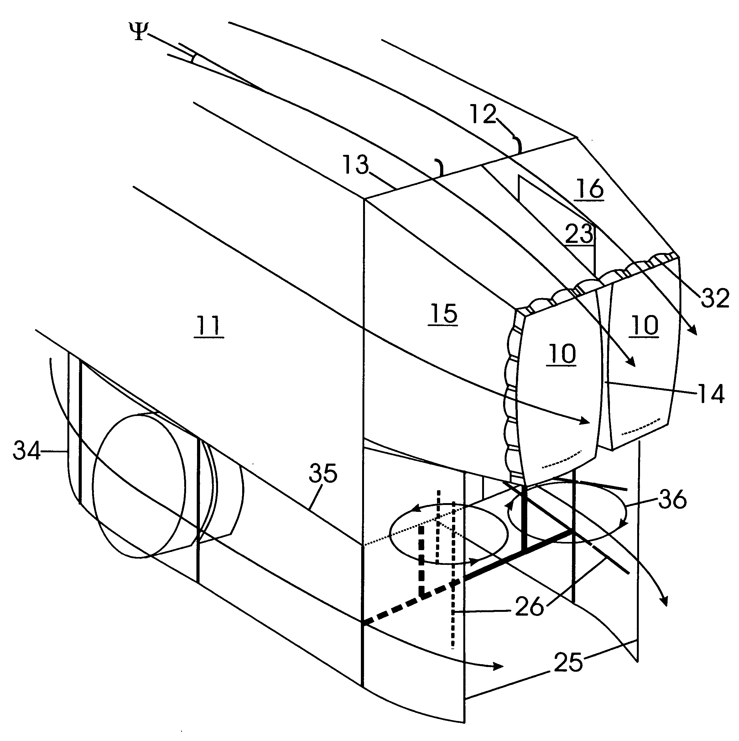
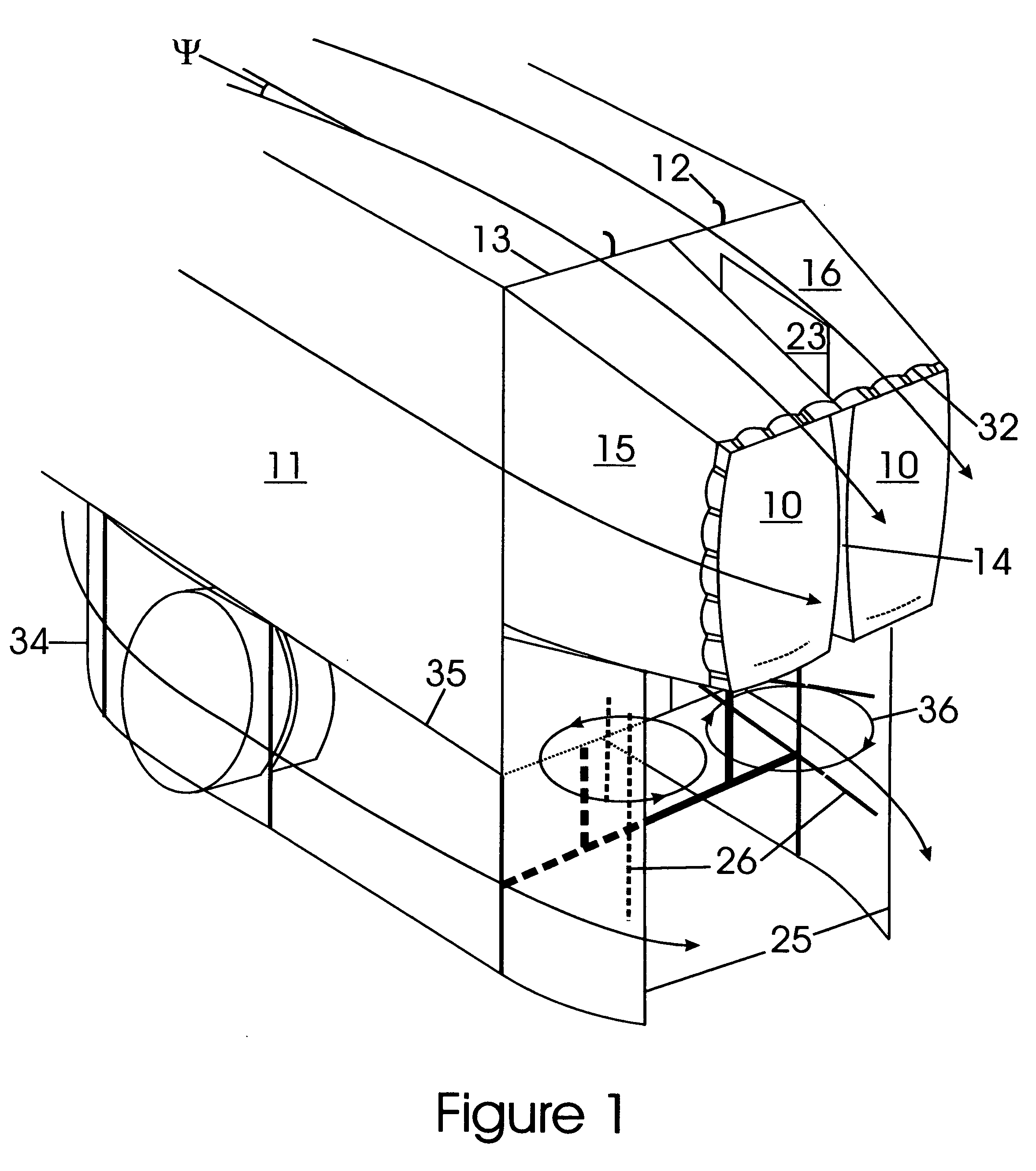
[0009] The device is comprised of a pair of inflatable bags 10 that are inflated upon forward motion of the trailer 11 by ram air intake scoops 12 that extend above the trailer roof line 13 from each bag 10. The bags 10 are pressed together along a central cleft 14 when inflated, and this union has a stabilising effect on the apparatus. The boattail 15 and backlight 16 surfaces are reinforced by a series of staggered interrupted ribs 17 to create rigidity during inflation, while enabling complex folding during deflation. A boattail shelf 18 is fixed to the boattail surface 15 and extends forwardly to meet the trailer side 19. The boattail surface 15 is anchored to the medial edge 20 of the base of each bag via a series of cords 21 that extend radially from the medial edge 20 to the boattail surface 15. A backlight shelf 22 is fixed to the backlight surface 16 and extends forwardly to meet the trailer roof line 13, and medially to meet the opposite shelf. A yaw control fin 23 is hing...


PUM


Abstract

A twin bag inflatable rear airfoil for truck or transport trailer with attached shelves that bridge the surface gap between the trailer side and top surfaces, and the corresponding side and top surfaces of the inflatable bags. Shelves also bridge the upper surface gap between the two bags and provide a platform to deploy a collapsible yaw control fin. Another set of panels provide airfoil surfaces in the ground domain and are integral to the organised automatic folding and stowage of the apparatus. Interrupted ribs stiffen the inflatable surfaces while allowing them to fold in an orderly manner.

Description

BACKGROUND OF THE INVENTION [0001] The reduction in aerodynamic drag resulting from the addition of a boattail shaped appendage to a boxed shaped vehicle has been well examined. Drag reductions of 30% are realistically possible (NASA / TP-1999-206574, “A Reassessment of Heavy-Duty Truck Aerodynamic Design Features and Priorities”), and would correspond to fuel savings of 15% for a transport truck. There are however several practical requirements that pose difficulties to implementing such a device on a working transport trailer. The device must not impede the operation of the trailer doors, typically swinging double doors on trailers used for long-distance haulage. The device must present a smooth, gently tapering set of boattail (side) and backlight (top) surfaces that connect tightly to the trailer sides and top respectively for optimum aerodynamic performance. Given practical difficulties in tightly fitting an inflatable to the hardware laden trailer door perimeter, the present inv...

Claims


Application Information

Patent Timeline
Patent Type & Authority Applications(United States)
IPC IPC(8): B62D35/00
CPCB62D35/004
Inventor ANDRUS, PAUL GUYCAMPBELL-ANDRUS, GAYLE
Owner ANDRUS PAUL GUY
Why Eureka
Try Eureka