Apparatus and method for optically detecting an object

an apparatus and optical imaging technology, applied in the direction of optical light guides, lifting machines, lifting devices, etc., can solve the problems of optical device overall optical error as small, optical component error, and never exactly achieved the optical theoretic optical axis, so as to achieve the effect of reducing the overall optical error of the apparatus

Inactive Publication Date: 2006-12-07
VISTEC SEMICON SYST
View PDF7 Cites 5 Cited by
  • Summary
  • Abstract
  • Description
  • Claims
  • Application Information

AI Technical Summary

Benefits of technology

[0007] It is therefore an object of the present invention to provide and improve an apparatus and method of the initially mentioned type, wherein the overall error of the optical imaging of the apparatus is further reduced and ideally minimized.

Problems solved by technology

In practice, this optimal theoretic optical axis is never exactly achieved even with optimized manufacturing conditions and precise assembly in the optical devices.
Furthermore it is assumed that the errors of the optical components occur with a radial symmetry, which is not usually the case.
The individual optical components are centered and adjusted within themselves before assembly in the optical devices in such a way that the optical device has an overall optical error which is as small as possible.
The result is that errors inherent in the calibrating interferometer itself are compensated by each optical component to be adjusted and is therefore transferred to the optical component itself In the end, an optical component has itself a residual error.

Method used


Image

  • Apparatus and method for optically detecting an object
  • Apparatus and method for optically detecting an object
  • Apparatus and method for optically detecting an object

Examples


Embodiment Construction

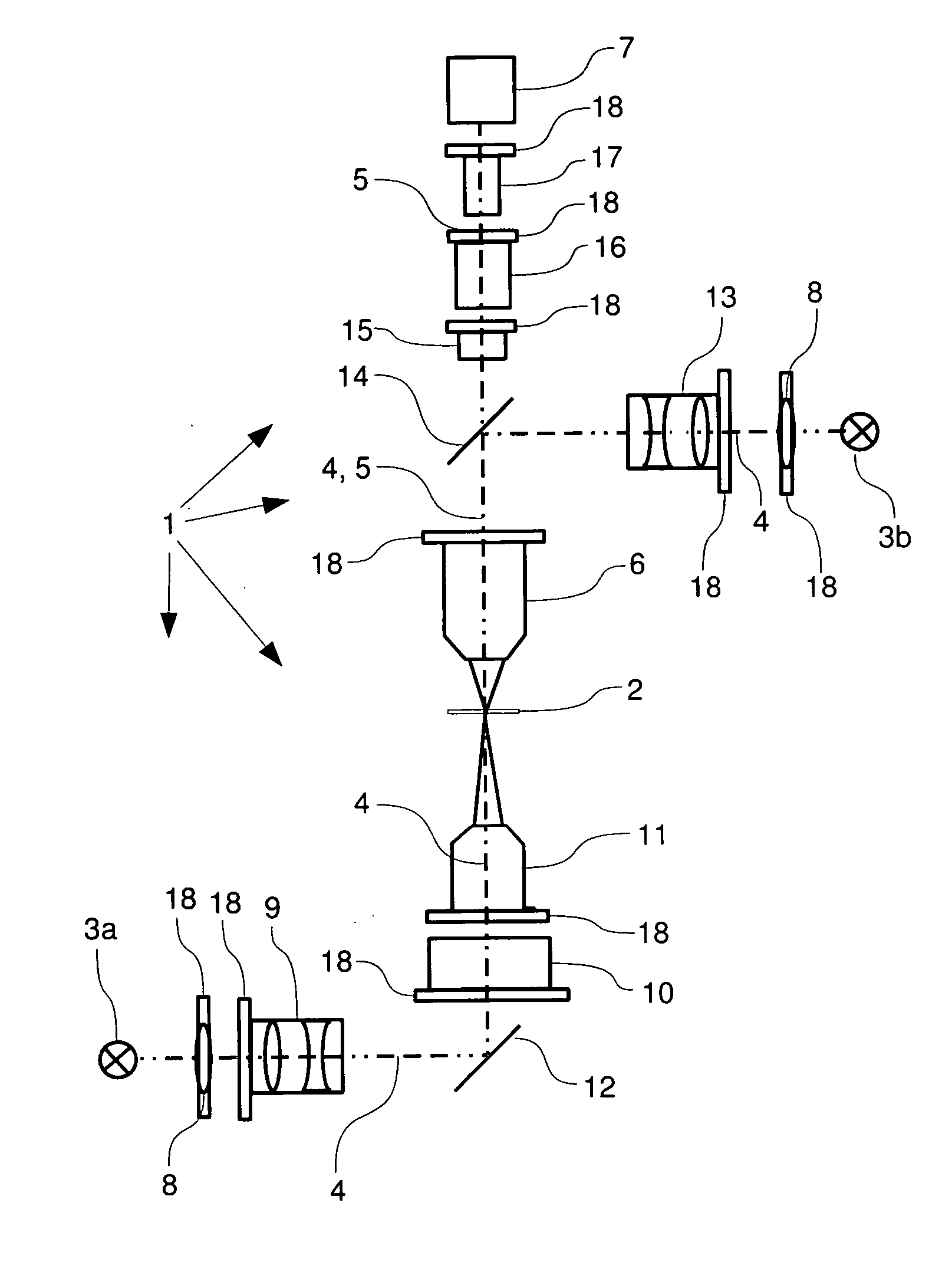
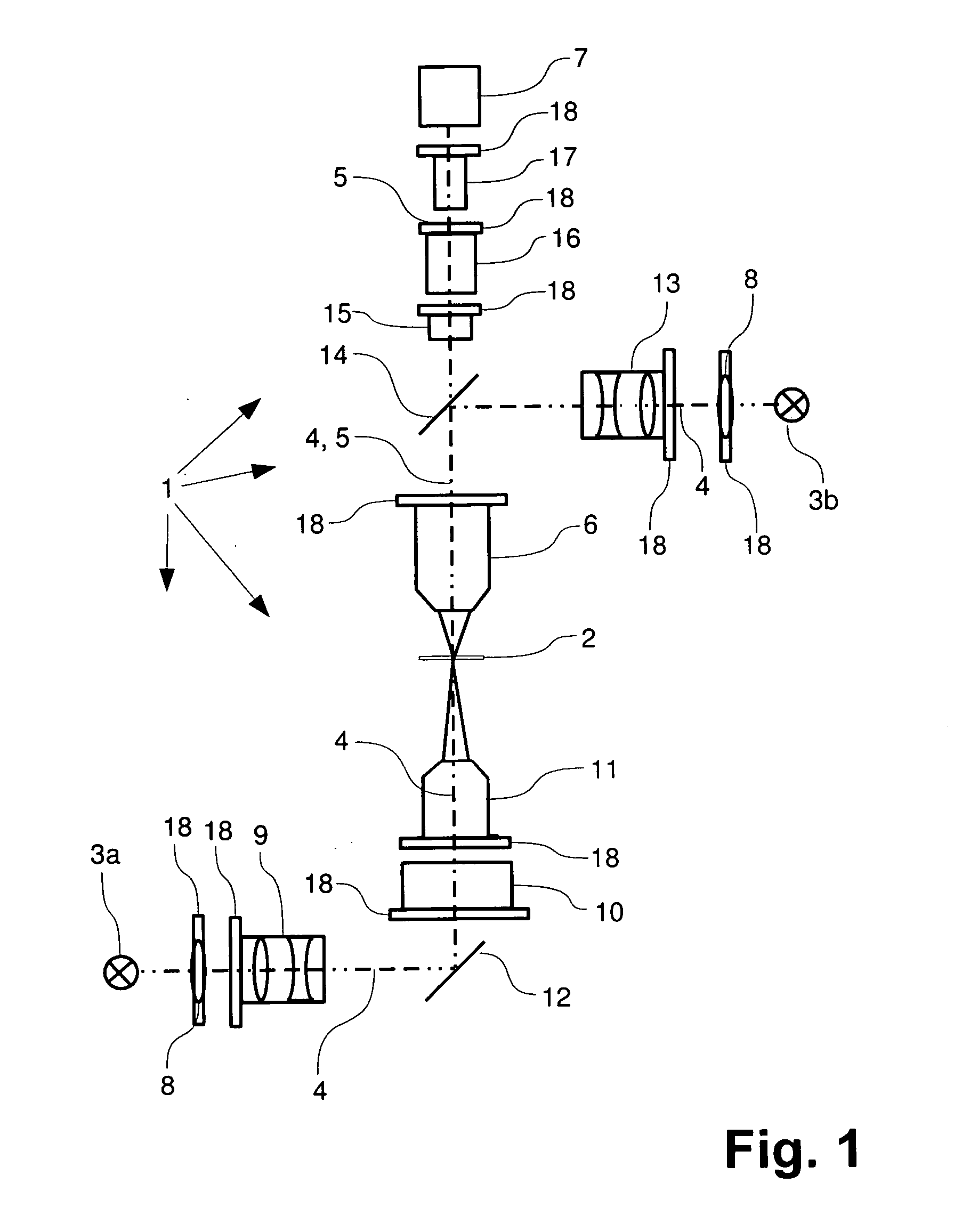
[0038]FIG. 1 shows an exemplary embodiment of an apparatus 1 according to the present invention for detecting an object 2. Apparatus 1 comprises two light sources 3a, 3b, an illumination optical path 4, a detection optical path 5, imaging optics 6 in the form of a microscope lens, and a detection means 7 in the form of a CCD camera. Apparatus 1 serves to detect object 2 by means of transmitted-light and / or incident-light illumination. To detect object 2 in the transmitted-light mode, object 2 is lighted by light source 3a. To detect object 2 in the incident-light mode, object 2 is lighted by light source 3b. Correspondingly, the illumination optical path 4 for the transmitted-light illumination extends from light source 3a to object 2. The illumination optical path 4 for the incident-light illumination extends from light source 3b to object 2. The detection optical path 5 extends from object 2 to detecting means 7.

[0039] The light emitted by light source 3a is at least partially co...


PUM


Abstract

Apparatus and method for optically detecting an object. The apparatus includes a light source to illuminate an object, an illumination optical path, a detection optical path, imaging optics, a detection means, wherein the imaging optics are arranged in the detection optical path and wherein light from the object can be imaged onto the detection means with the aid of the imaging optics, an adjustment means is provided, by means of which at least one imaging optical component, arranged in the illumination optical path or in the detection optical path, is rotatable about its respective optical axes, or is pivotable with respect to the optical axis of the optical path in which the optical component is arranged, and is translatable in a direction transverse to the optical axis, to detect an object with the aid of the optical component in a rotated, pivoted or translated state.

Description

CROSS REFERENCE TO RELATED APPLICATIONS [0001] This patent application claims priority of German Patent Application No. 10 2005 023 973.0, filed on May 20, 2005, which application is incorporated herein by reference. FIELD OF THE INVENTION [0002] The present invention relates to an apparatus for optically detecting an object. The apparatus comprises a light source, an illumination optical path, a detection optical path, imaging optics, and a detection means. An object can be illuminated by means of the light source. The imaging optics are arranged within the detection optical path. Light coming from the object can be imaged onto the detection means by using the imaging optics. The present invention further relates to a method for optically detecting an object. BACKGROUND OF THE INVENTION [0003] In the prior art it has been common to align fixed, and, in particular, error-minimized, optical components as precisely as possible along an optical axis, which in an optical apparatus is pr...

Claims


Application Information

Patent Timeline
Patent Type & Authority Applications(United States)
IPC IPC(8): G02B6/00A01D27/04
CPCG02B27/00G02B21/00
Inventor SULIK, WOLFGANGBOESSER, HANS-ARTUR
Owner VISTEC SEMICON SYST
Why Eureka
Try Eureka