Microscope objective with axially adjustable correction mounts

a technology of axial adjustment and correction mount, which is applied in the direction of mounting, microscope, optics, etc., can solve the problems of reducing the movability of the rotatable structural components, unable to integrate the helical spring within the limited space of the microscope objective, and the helical spring is subjected to twisting stress, so as to achieve the effect of minimizing optical imaging errors and small structural length of the objectiv

Active Publication Date: 2005-08-04
CARL ZEISS MICROSCOPY GMBH
View PDF6 Cites 3 Cited by
  • Summary
  • Abstract
  • Description
  • Claims
  • Application Information

AI Technical Summary

Benefits of technology

[0012] It is the primary object of the present invention to provide a microscope objective with correction mounts which enables adjustments for purposes of compensating parameters which influence imaging quality while retaining a small structural length of the objective and in which optical imaging errors are minimized in that the parts move relative to one another without play.

Problems solved by technology

Due to the large number of moving parts and the resulting frictional resistances and weight forces, the required spring force is usually so large that it is scarcely possible to use a conventional helical spring.
A helical spring of this kind cannot be integrated within the limited space of a microscope objective.
In so doing, an individual helical spring is subjected to twisting stress which has a negative impact on the movability of the rotatable structural component parts.
It is disadvantageous that every pressure spring is integrated in a sleeve for guiding in order to prevent the springs from buckling.
Nevertheless, since the pressure springs are not completely guided in the sleeve in the interest of ensuring the spring path, buckling can occur in the exposed area.
In this construction, none of the contact surfaces of the individual springs may be subjected to a rotating movement because this would result in a buckling of the springs.

Method used


Image

  • Microscope objective with axially adjustable correction mounts
  • Microscope objective with axially adjustable correction mounts
  • Microscope objective with axially adjustable correction mounts

Examples


Embodiment Construction

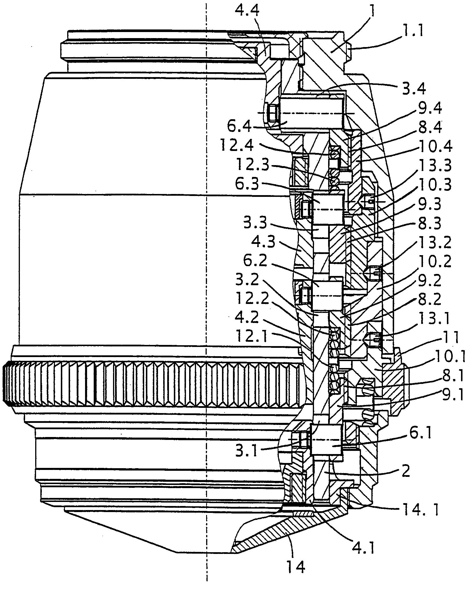
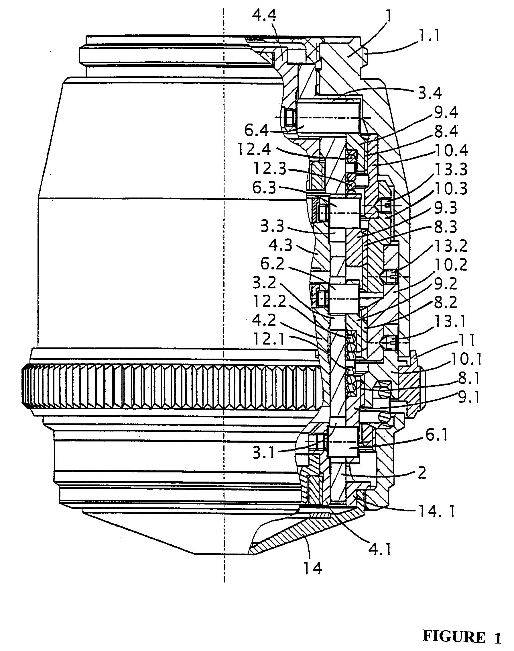
[0031] The microscope objective shown in partial section in FIG. 1 comprises a barrel 1 provided with a screw-in thread 1.1 and with an inner cylindrical sleeve 2 which is fixedly connected to the latter and which has axially directed through-openings 3.1 to 3.4 and in which precision, axially adjustable correction mounts 4.1 to 4.4 are arranged. In this embodiment example, four correction mounts 4.1 to 4.4 are provided. In principle, it is also conceivable to provide more than four, but at least three, correction mounts. Depending on the quantity of correction mounts provided in the objective, the cylindrical sleeve 2 also has a corresponding quantity of through-openings. The quantity of structural component parts cooperating with the correction mounts also depends on the quantity of correction mounts. The individual optical elements (not shown) comprising individual lenses and / or lens groups are fixedly held in these correction mounts 4.1 to 4.4. A radially directed bolt 6.1 to 6....


PUM


Abstract

The invention is directed to a microscope objective with axially adjustable correction mounts and is applicable in connection with different cover slips and/or different immersion liquids and/or at different work temperatures. In the microscope objective according to the invention, helical springs which are uniformly distributed along the circumference and act in axial direction are fixed by a first ring which has pins in axial direction on which the helical springs are arranged. The pins engage in bore holes of a second ring. The bore holes are at least deep enough to ensure the required spring path. The two rings with the helical springs arranged therebetween on the pins form a spring retainer which ensures a movement of the parts without play and/or in a springing manner. In principle, the proposed solution can be substituted for all pressure springs in microscope objectives and other objectives and can overcome the disadvantages of using individual springs.

Description

CROSS-REFERENCE TO RELATED APPLICATION [0001] This application claims priority of German Application No. 103 61 912.7, filed Dec. 24, 2003, the complete disclosure of which is hereby incorporated by reference. BACKGROUND OF THE INVENTION [0002] a) Field of the Invention [0003] The invention is directed to a microscope objective with axially adjustable correction mounts in which lenses or lens groups are arranged, particularly for live cell imaging and for cell culture and tissue culture research. The invention is applicable in microscope objectives in connection with different cover slips and / or different immersion liquids and / or at different work temperatures. [0004] b) Description of the Related Art [0005] With these kinds of axial adjustments of optical elements in objectives, different kinds of corrections can be carried out in order to enable microscopic examinations under various conditions with high quality and high lateral magnifications. [0006] In microscope objectives, the...

Claims


Application Information

Patent Timeline
Patent Type & Authority Applications(United States)
IPC IPC(8): G02B7/02G02B21/02
CPCG02B21/02G02B7/023
Inventor HERBST, GEORGOZIMEK, HEINZ-GUENTHERFAHLBUSCH, INGOHENKEL, HEINZ-HERMANNALBRECHT, KLAUS-DIETER
Owner CARL ZEISS MICROSCOPY GMBH
Why Eureka
Try Eureka