Ultraviolet curing equipment and method for optical fiber coating

A technology for optical fiber coating and curing equipment, applied in the field of optical fiber manufacturing equipment, can solve the problems of increasing the complexity of equipment structure, low utilization rate of mercury lamp energy, insufficient curing uniformity, etc., and achieves large light source layout space and high curing efficiency. , The effect of good curing uniformity

Active Publication Date: 2013-09-25
YANGTZE OPTICAL FIBRE & CABLE CO LTD
View PDF3 Cites 41 Cited by
  • Summary
  • Abstract
  • Description
  • Claims
  • Application Information

AI Technical Summary

Problems solved by technology

Mercury lamps have the disadvantage of requiring considerable power to produce UV radiation of sufficient intensity
For example, curing a single-coated fiber (such as polymer coating) may require a total power consumption of 50kW
Another disadvantage of mercury lamps is that a large amount of energy used to light mercury lamps is emitted as heat instead of ultraviolet rays, which means that mercury lamps have a relatively low energy utilization rate
This method follows the concentrating method of the traditional mercury lamp curing equipment, but the mercury lamp tube emits light in a 360-degree direction, while the output of UVLED is limited in direction. There may be insufficient curing uniformity; in order to solve the problem of insufficient curing uniformity, this patent proposes to arrange the UVLED light source in a spatial spiral array in a multi-section curing cavity, which will undoubtedly increase the complexity of the equipment structure
In addition, the curing equipment proposed in this patent uses a single-sided UVLED light source in each section of the curing cavity, which may also have the possibility of insufficient UV light intensity and insufficient curing efficiency.

Method used


Image

  • Ultraviolet curing equipment and method for optical fiber coating
  • Ultraviolet curing equipment and method for optical fiber coating
  • Ultraviolet curing equipment and method for optical fiber coating

Examples


Embodiment 1

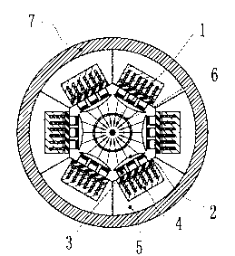
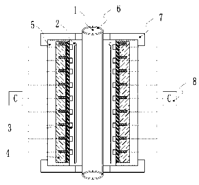
[0035] Embodiment 1: as Figure 1-3As shown, it includes a cylindrical installation base, and the cylindrical installation base is formed by splicing 6 strip-shaped arc blocks 5 along the circumferential direction, and is fixedly connected by upper and lower fixed end plates 7, and each strip The inner surface of the arc-shaped block is embedded with a UVLED light source module, so that the inner cavity of the cylindrical mounting base is installed along the circumferential direction and the axial direction. The UVLED light source module includes a UVLED light source 3 and a radiator 4. The wavelength of the light source is 365nm and 375nm, and the radiator is a liquid medium radiator; the UVLED light source module is connected with the control module 8 to control and adjust the intensity of ultraviolet light emitted by each UVLED light source module; the UVLED light source includes The UVLED array is equipped with a cylindrical focusing lens 2 in front of the UVLED light sour...

Embodiment 2

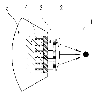
[0036] Embodiment 2: as Figure 4-5 As shown, it differs from the previous embodiment in that the cylindrical mounting base is in the shape of a hexagonal cylinder, and is formed by splicing six strip-shaped trapezoidal blocks 5 along the circumferential direction. Other structures are the same as the previous embodiment.

Embodiment 3

[0037] Embodiment 3: as Figure 6 As shown, it differs from the first embodiment in that the cylindrical mounting base is spliced ​​by 4 strip-shaped arc blocks evenly spaced along the circumference, and on the inner surface of each strip-shaped arc block The UVLED light source modules are embedded so that the UVLED light source modules are evenly spaced along the inner cavity of the cylindrical mounting base. Other structures are the same as the first embodiment.


PUM

PropertyMeasurementUnit
wavelengthaaaaaaaaaa

Abstract

The invention relates to ultraviolet curing equipment and method for an optical fiber coating. The equipment comprises a cylindrical mounting base, wherein an inner cavity of the cylindrical mounting base is provided with UVLED (Ultraviolet Light Emitting Diode) light source modules in a peripheral direction and an axial direction; a cylindrical focusing lens is arranged in front of light-emitting surfaces of the UVLED light source modules, so that ultraviolet rays emitted from the UVLED light source modules are focused on a same curing axis. The ultraviolet curing equipment disclosed by the invention is long in service life, small in heating amount and low in energy consumption; a layout space of light sources is large, so that the output of the UV light sources of a plurality of UVLED light source modules are focused on the curing axis to form a UV light column with high light intensity; an optical fiber absorbs UV and is cured when passing through the UV light column; the light strength of the light column is high and the light sources are from multiple directions, so that the equipment has higher curing efficiency and better curing uniformity, the curing time is shortened, the work efficiency of wiredrawing of the optical fiber is improved, and the curing quality of the coating is improved.

Description

technical field [0001] The invention relates to a device and method for efficiently curing the coating layer of a high-speed drawn optical fiber, and belongs to the technical field of optical fiber manufacturing equipment. Background technique [0002] The outside of the optical fiber usually has one or several layers of coating as its protective layer. In a typical optical fiber drawing process, when the preform is melted and drawn into a bare optical fiber, two or more layers of coatings need to be coated on-line. Usually a relatively soft inner coating prevents microscopic bending of the fiber, and a relatively hard outer coating provides additional protection and better handling of the fiber. These organic polymer coatings can be cured onto the fiber surface by heat (thermal curing) or exposure to ultraviolet light (UV curing). Ultraviolet (UV) curing of optical fiber coating refers to the use of ultraviolet rays to trigger rapid polymerization and crosslinking of liqu...

Claims


Application Information

Patent Timeline
Patent Type & Authority Applications(China)
IPC IPC(8): C03C25/64
Inventor 乐正卢松涛曹蓓蓓李国巍
Owner YANGTZE OPTICAL FIBRE & CABLE CO LTD
Why Eureka
Try Eureka