
Gutter and roof protection system

a gutter cover and gutter technology, applied in the direction of roof coverings, roofs, roofs, etc., can solve the problems of limiting the ability of gutters to collect water, the accumulation of snow and ice on roofs, and the fascia and soffits of buildings are also subject to snow and ice accumulation, so as to prevent the accumulation of snow and ice effectively and efficiently

Inactive Publication Date: 2006-12-14
BACHMAN JAMES E
View PDF83 Cites 55 Cited by
  • Summary
  • Abstract
  • Description
  • Claims
  • Application Information

AI Technical Summary

Benefits of technology

[0009] The present invention solves the above-described problems and provides a distinct advance in the art of gutter covers and heating cables. More particularly, the present invention provides a gutter and roofprotection system which more effectively and efficiently prevents the clogging of gutters and the formation of ice dams.
[0011] The heating element is placed within the channel and then connected to a suitable source of electricity so as to melt snow and ice which accumulates on or near the gutter cover. The channel is advantageously positioned so that it places the heating cable near portions of the gutter cover and gutter that are spaced furthest from the building. This directs heat to areas that are most subject to the formation of ice dams because of their spacing from the building and any heat emitted therefrom. The channel also retains the heating element and prevents it from moving, without the use of fasteners. The channel also positions the heating element so that it doesn't impede the normal flow of water over the gutter cover or through the gutter or collect debris.
[0015] All embodiments of the present invention effectively prevent the formation of ice dams on gutters and gutter covers without the use of wasteful amounts of heating cable and electricity. By using less heating cable and / or lower voltage cable, the present invention also reduces fire risks.

Problems solved by technology

Unfortunately, gutters often become clogged with leaves, twigs, and other debris, thus limiting their ability to collect water.
Clogged gutters can also overflow, causing water damage to fascia and soffits of the buildings to which they are attached.
Roofs and other sloped surfaces are also subject to the accumulation of snow and ice, especially on eaves and overhangs which are not positioned over heated areas.
Accumulated snow and ice can cause “ice dams” on roofs, gutters, and gutter covers which interfere with the normal shedding and collection of water.
Over prolonged periods of time, the freezing and subsequent thawing cycle of the water expands these cracks, eventually damaging the roof and underlying materials.
Such ice dams also often break away and fall to the ground, potentially causing injury to persons and damage to property below.
However, heating cables must be fastened with staples, nails or other fasteners or they will move over time and require repositioning.
Use of such fasteners creates holes in the roofs and / or gutters, resulting in damage due to water infiltration and the subsequent freezing and thawing described above.
This placement of heating cables on top of roof shingles and gutters also creates an impediment to the normal flow of water and can trap leaves and other debris.
Heating cables and other de-icing products can be installed underneath roof shingles to avoid some of the above-described problems, but doing so requires a great deal of labor, especially for existing roofs.
Covering heating cables with shingles also reduces their ability to melt snow and ice, increases the risk of fires, and may cause the shingles to become dislodged from the roof over time.
Heating cables are also typically installed in a way that reduces their effectiveness and requires the use of excessive lengths of the cable and / or wasteful power levels.
Both of these solutions waste energy and cable and increase fire hazards.

Method used


Image

  • Gutter and roof protection system
  • Gutter and roof protection system
  • Gutter and roof protection system

Examples


Embodiment Construction

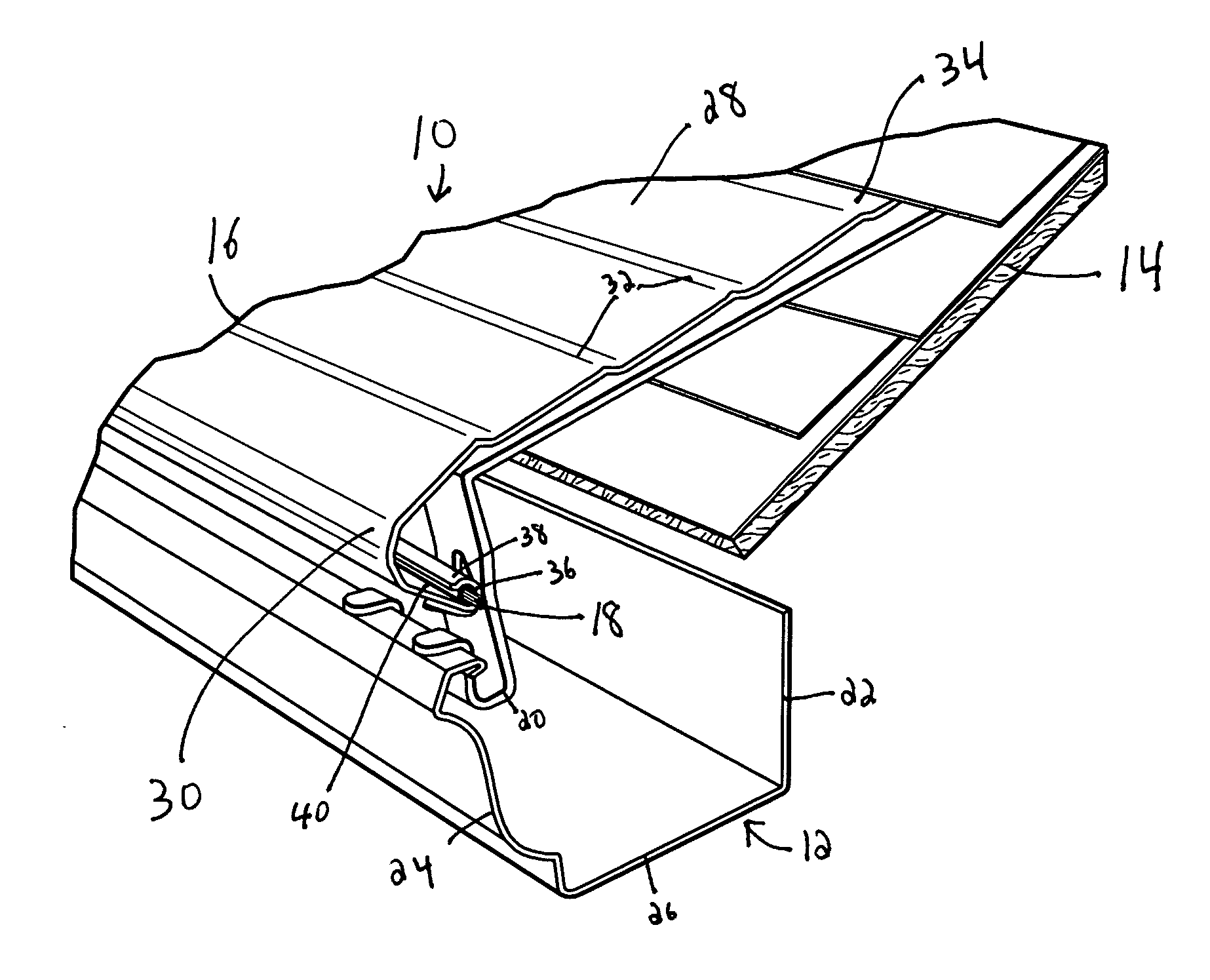
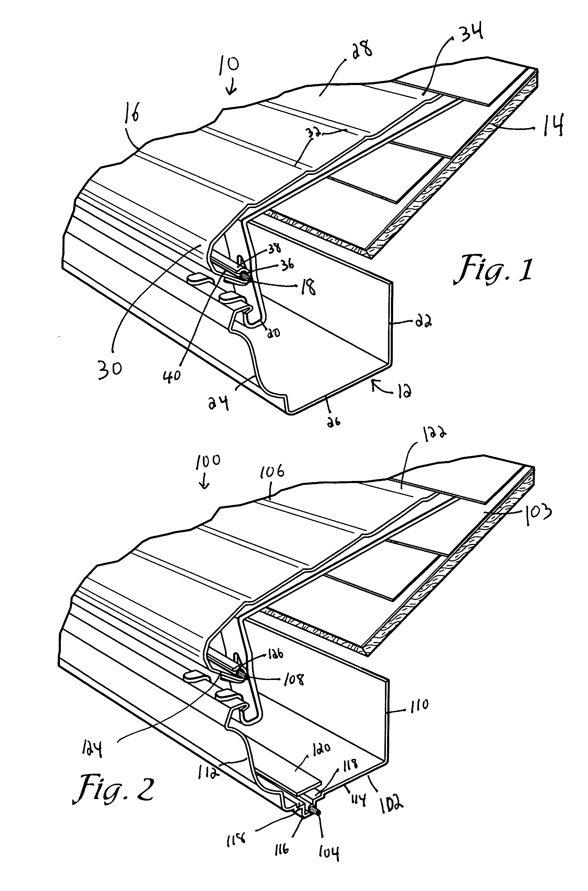
[0022]FIG. 1 illustrates a gutter and roof protection system 10 constructed in accordance with a first preferred embodiment of the present invention. The system 10 is adapted to be installed over a gutter 12 affixed to a roof 14 or other sloped surface of a building or other structure and broadly includes a gutter cover 16 and a heating element 18. The system 10 may also include one or more mounting brackets 20 for supporting the gutter cover 16 over the gutter 12, one or more end caps for capping the ends of the gutter cover, and one or more diverter elements for use at converging sloped roof locations.

[0023] The gutter 12 over which the system 10 is mounted is conventional and may include a rear wall 22 for attachment to a soffit or other part of the building; a front wall 24 spaced from the rear wall 22 and the building; and a bottom wall 26 extending between a lower edge of the rear wall and a lower edge of the front wall. The particular gutter 12 shown and illustrated herein i...


PUM


Abstract

A gutter and roof protection system includes a gutter cover and a heating element. The gutter cover is installed over a gutter attached to a roof or other sloped surface of a building and includes a first end configured to be positioned over or under a row of shingles on the roof and an opposite, second end configured to be positioned over a portion of the gutter which is spaced from the roof. The second end includes an elongated, partially enclosed channel. The heating element is placed within the channel and then connected to a suitable source of electricity so as to melt snow and ice which accumulates on or near the gutter cover. The channel on the second end of the gutter cover is positioned so that it places the heating cable near portions of the gutter cover and gutter that are spaced furthest from the building.

Description

BACKGROUND OF THE INVENTION [0001] 1. Field of the Invention [0002] The present invention relates to gutters, gutter covers, and ice and snow melting systems. More particularly, the invention relates to a gutter and roof protection system with at least one heating element. [0003] 2. Description of the Prior Art [0004] Gutters are often installed on houses and other buildings to collect and carry water away from roofs and other sloped surfaces. Unfortunately, gutters often become clogged with leaves, twigs, and other debris, thus limiting their ability to collect water. Clogged gutters can also overflow, causing water damage to fascia and soffits of the buildings to which they are attached. Gutter covers, such as the ones described in U.S. Pat. Nos. 5,557,891; 5,660,001; and 6,098,344 have been developed to alleviate these problems. [0005] Roofs and other sloped surfaces are also subject to the accumulation of snow and ice, especially on eaves and overhangs which are not positioned o...

Claims


Application Information

Patent Timeline
IPC IPC(8): E04D13/00
CPCE04D13/0762E04D13/076
Inventor BACHMAN, JAMES E.
Owner BACHMAN JAMES E
Features
  • Generate Ideas
  • Intellectual Property
  • Life Sciences
  • Materials
  • Tech Scout
  • Unparalleled Data Quality
  • Higher Quality Content
  • 60% Fewer Hallucinations
Learn More