
Supplemental restraint deployment method with anticipatory crash classification

a technology of supplemental restraints and classification methods, applied in the direction of pedestrian/occupant safety arrangements, instruments, tractors, etc., can solve problems such as affecting the safety of pedestrians and occupants, and achieve the effect of reducing the cost of the system

Active Publication Date: 2006-12-14
APTIV TECH LTD
View PDF9 Cites 17 Cited by
  • Summary
  • Abstract
  • Description
  • Claims
  • Application Information

AI Technical Summary

Benefits of technology

The present invention is a method for deploying supplemental restraints in a vehicle that uses measured speed and acceleration, as well as information from a closing velocity sensor to detect the presence and closing rate of an approaching object. This method allows for the classification of a crash event and the determination of the appropriate level of restraint deployment based on the actual severity of the crash. The method also resets when the vehicle velocity changes back to the initial closing velocity. The technical effect of this invention is to improve the accuracy and effectiveness of supplemental restraint deployment in a vehicle during a crash event.

Problems solved by technology

The timeliness of crash discrimination and deployment can be improved through the addition of one or more remote acceleration sensors near the front of the vehicle, but this considerably increases system cost.
However, manufacturers have been reluctant to take any action based on the output of an anticipatory sensor because it is difficult or impossible to discriminate between objects that might result in a serious collision and objects that pose little or no danger to the vehicle occupants.

Method used


Image

  • Supplemental restraint deployment method with anticipatory crash classification
  • Supplemental restraint deployment method with anticipatory crash classification
  • Supplemental restraint deployment method with anticipatory crash classification

Examples


Embodiment Construction

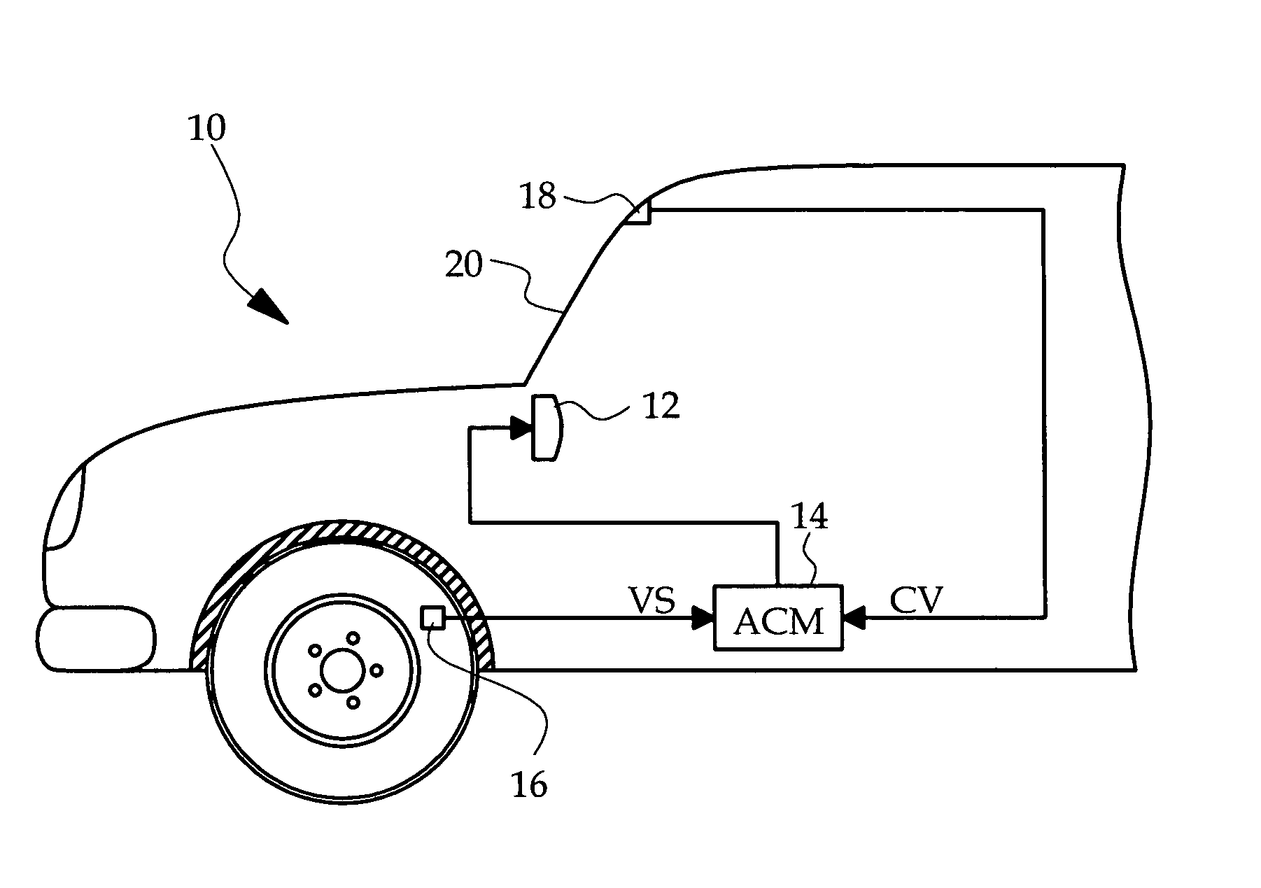
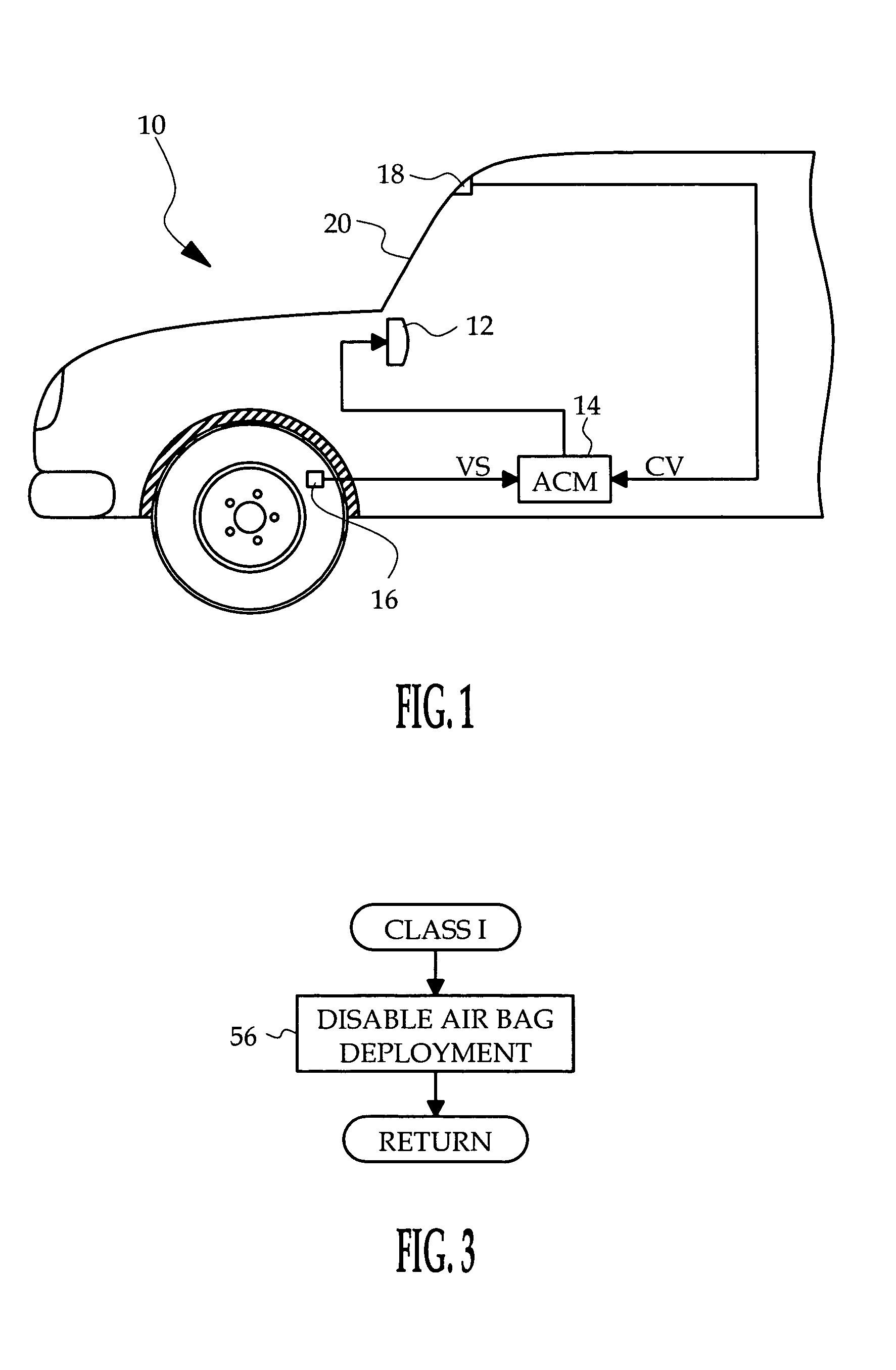
[0012] Referring to FIG. 1, the reference numeral 10 generally designates a vehicle including one or more multi-stage supplemental restraints 12 such as airbags and a microprocessor-based airbag control module (ACM) 14. The ACM 14 has an internal accelerometer responsive to longitudinal acceleration of the vehicle 10, and also receives input signals pertaining to vehicle speed (VS) and closing velocity (CV) of an approaching object. The vehicle speed input VS is obtained from one or more conventional wheel speed sensors 16, and the closing velocity input CV is obtained from a closing velocity sensor 18 mounted on the interior surface of the vehicle windshield 20. An example of a suitable closing velocity sensor 18 is the CV sensor manufactured by Continental Automotive Systems (TEMIC), for example. This CV sensor emits a coded laser beam in the forward path of the vehicle 10 and decodes beam components reflected from an approaching object to identify its existence and determine the ...


PUM


Abstract

A supplemental restraint deployment method utilizes measured vehicle speed and acceleration and the output of a closing velocity sensor that detects the presence and closing rate of an approaching object prior to contact with the vehicle. The closing velocity and vehicle speed are utilized for classification of an impending crash event, where the deployment options vary depending on the crash classification. In the ensuing crash event, a classification-dependent algorithm is executed to determine if, when and what level of restraint deployment is warranted based on measures of actual crash severity. Additionally, the algorithm is reset when the calculated change in vehicle velocity reaches the initial closing velocity.

Description

TECHNICAL FIELD [0001] The present invention relates to controlling the deployment of supplemental restraints such as airbags, and more particularly to a deployment method based on measured acceleration and closing velocity. BACKGROUND OF THE INVENTION [0002] Deployment algorithms for supplemental restraints such as airbags have traditionally relied almost exclusively on measured vehicle parameters such as acceleration and speed. In a typical approach, the onset of a crash event is detected when the longitudinal acceleration of the vehicle exceeds an initial threshold; in the course of the ensuing crash event, the vehicle's change in velocity is calculated by integrating the longitudinal acceleration and the airbags are deployed for occupant protection if and when the calculated change in velocity exceeds a time-varying velocity boundary curve (VBC). [0003] The timeliness of crash discrimination and deployment can be improved through the addition of one or more remote acceleration s...

Claims


Application Information

Patent Timeline
Patent Type & Authority Applications(United States)
IPC IPC(8): B60R21/32
CPCB60R21/0132B60R21/0156B60R2021/01231B60R21/0134B60R21/01332B60R21/01336
Inventor CASHLER, ROBERT J.SHEN, JUNQIANGKOSIAK, WALTER KIRKSIMPSON, RUSSELL L.CLUFF, CHARLES A.
Owner APTIV TECH LTD
Learn More