Tank cap of fuel tank

Active Publication Date: 2006-12-28
KAWASAKI MOTORS LTD
View PDF17 Cites 7 Cited by
  • Summary
  • Abstract
  • Description
  • Claims
  • Application Information

AI Technical Summary

Benefits of technology

[0013] In accordance with the structure, since the concave portion can be formed large, it is

Problems solved by technology

In the case mentioned above, since it is necessary to take off th

Method used


Image

  • Tank cap of fuel tank
  • Tank cap of fuel tank
  • Tank cap of fuel tank

Examples


Example

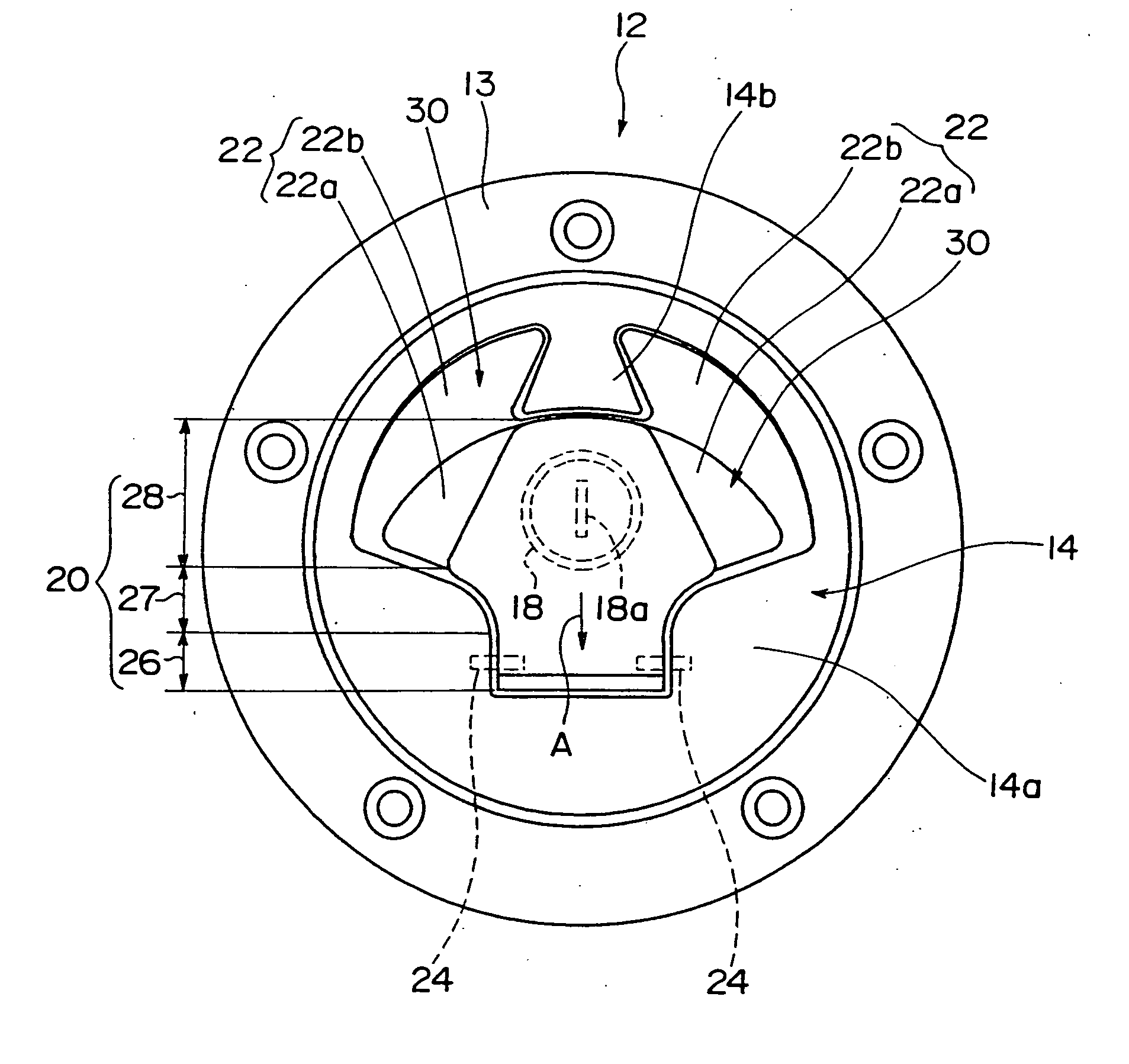
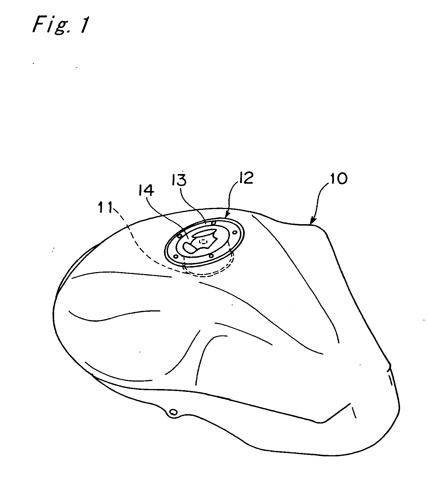
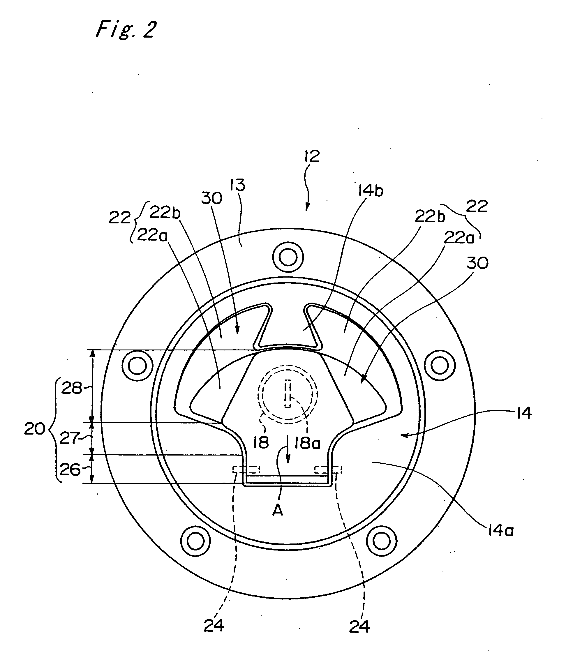
[0022]FIG. 1 is a perspective view showing a fuel tank of a motorcycle. The fuel tank 10 is arranged on a front side of a rider seat on an upper side of an engine of the motorcycle. On an upper surface of the fuel tank 10, a fuel supply port 11 is formed and a tank cap 12 for closing the fuel supply port 11 is provided. The tank cap 12 is provided with a circular ring-shaped base member 13 fixed to the fuel tank 10, and a cap main body 14 pivoted to the base member 13 so as to freely swing.

[0023]FIG. 4 is a front elevational view (a partly cross sectional view) of the tank cap 12, and FIG. 5 is a side elevational view (a partly cross sectional view) of the tank cap 12. As shown in FIG. 5, the cap main body 14 is pivoted to the base member 13 via a hinge 16 provided on the base member 13 so as to freely swing up and down, and can be opened and closed up and down. A lower portion of the cap main body 14 is provided with a pair of lock pieces 17 which can move forward and backward in ...


PUM


Abstract

Disclosed is a tank cap of a fuel tank which can easily open a cover covering a key hole. A tank cap for closing a fuel supply port of a fuel tank is provided on an upper surface of the tank cap with a key hole and a cover covering the key hole. The cover opens and closes the key hole by making the cover swing via a support shaft. Finger catch concave portions are formed at least on both sides of the cover in an axial direction of the support shaft, and each of the finger catch concave portions is structured such that it is possible to insert a finger thereinto and to pinch both side edges in the axial direction of the cover by the inserted finger. Further, a leading end portion of the cover is preferably formed in a tapered shape in a plan view.

Description

BACKGROUND OF THE INVENTION [0001] 1. Field of the Invention [0002] The present invention relates to a tank cap of a fuel tank which is mainly applied to a motorcycle, an all train vehicle or other vehicle. More particularly, the present invention relates to a tank cap which is suitable for a vehicle in which a fuel supply port of a fuel tank is exposed to an outer side, such as a motorcycle or the like. [0003] 2. Description of the Related Art [0004] A fuel tank arranged on an upper side of an engine of a motorcycle and on a front side of a rider seat is generally provided with a fuel supply port on an upper surface, and a tank cap is provided in the fuel supply port so as to be freely opened and closed. [0005]FIG. 7 is a plan view showing a conventional tank cap. A tank cap 101 is provided with a circular ring-shaped base member 102 fixed to an upper surface of a fuel tank, and a cap main body 103 coupled to the base member 102 via a hinge, and the cap main body 103 is provided wi...

Claims


Application Information

Patent Timeline
IPC IPC(8): E05B17/18
CPCB60K15/0409E05B83/34E05B17/183B60Y2200/12Y10T70/5558Y10T70/7955Y10T70/8649
Inventor YONEMURA, TOSHIHIROKAWAMURA, HIDETAKASHIBUTA, YU
Owner KAWASAKI MOTORS LTD
Why Eureka
Try Eureka