Eureka AIR delivers breakthrough ideas for toughest innovation challenges, trusted by R&D personnel around the world.

Tunable resonant cable trap

Inactive Publication Date: 2006-12-28
INVIVO CORP
View PDF6 Cites 6 Cited by
  • Summary
  • Abstract
  • Description
  • Claims
  • Application Information

AI Technical Summary

Problems solved by technology

In applications where there are intense external electrical / magnetic fields, for example, in magnetic resonance imaging (MRI), significant current may be induced in the shield, causing failure of the shielding effect and possibly damage to the shield and its adjacent insulation from heating.
These breaks, however, reduce the shielding effectiveness of the enclosure, and the exposed capacitors provide a potential site for coupling.
In such traps, it is sometimes difficult to achieve enough impedance through the magnetic coupling to provide an effective trap.

Method used


Image

  • Tunable resonant cable trap
  • Tunable resonant cable trap
  • Tunable resonant cable trap

Examples


Embodiment Construction

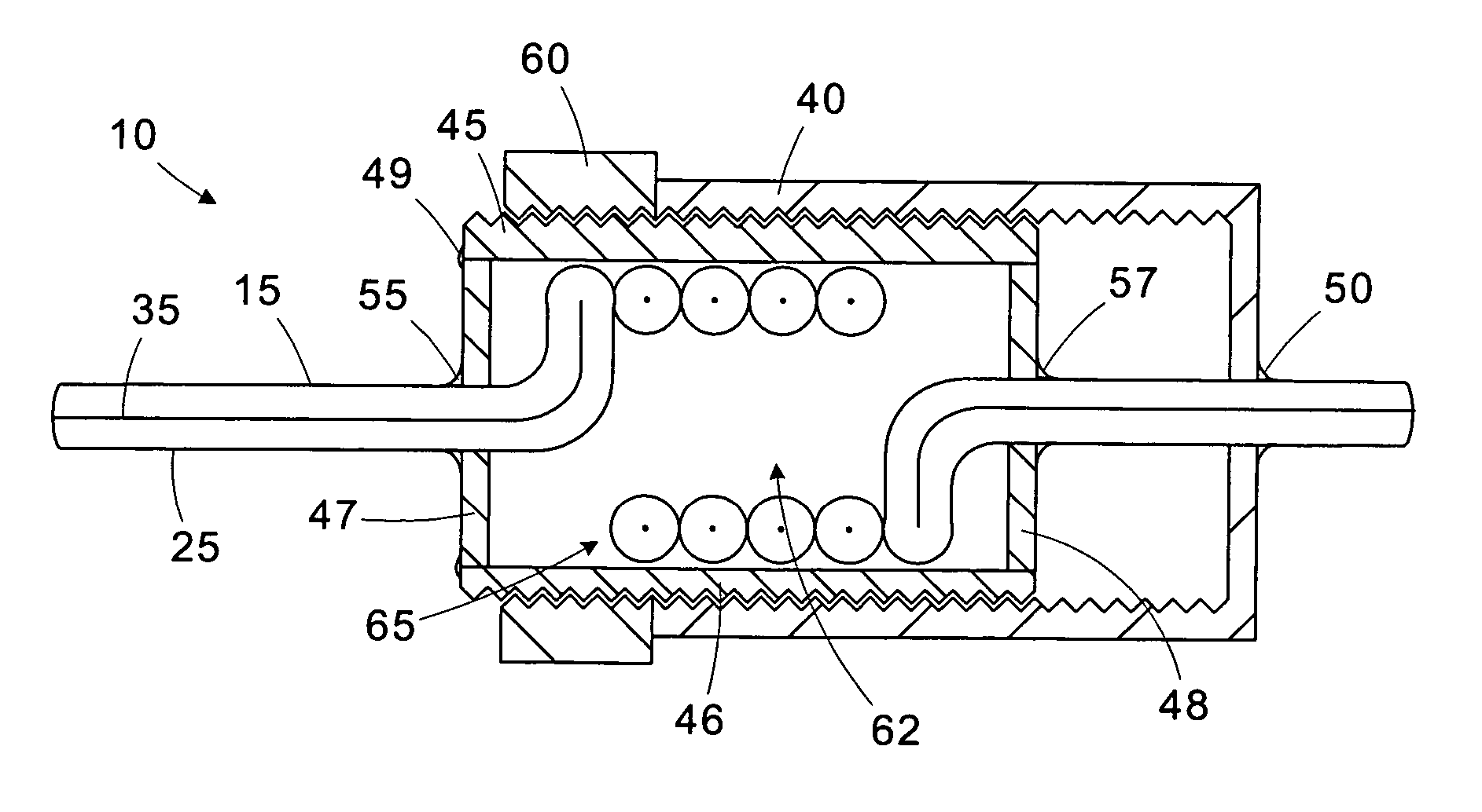
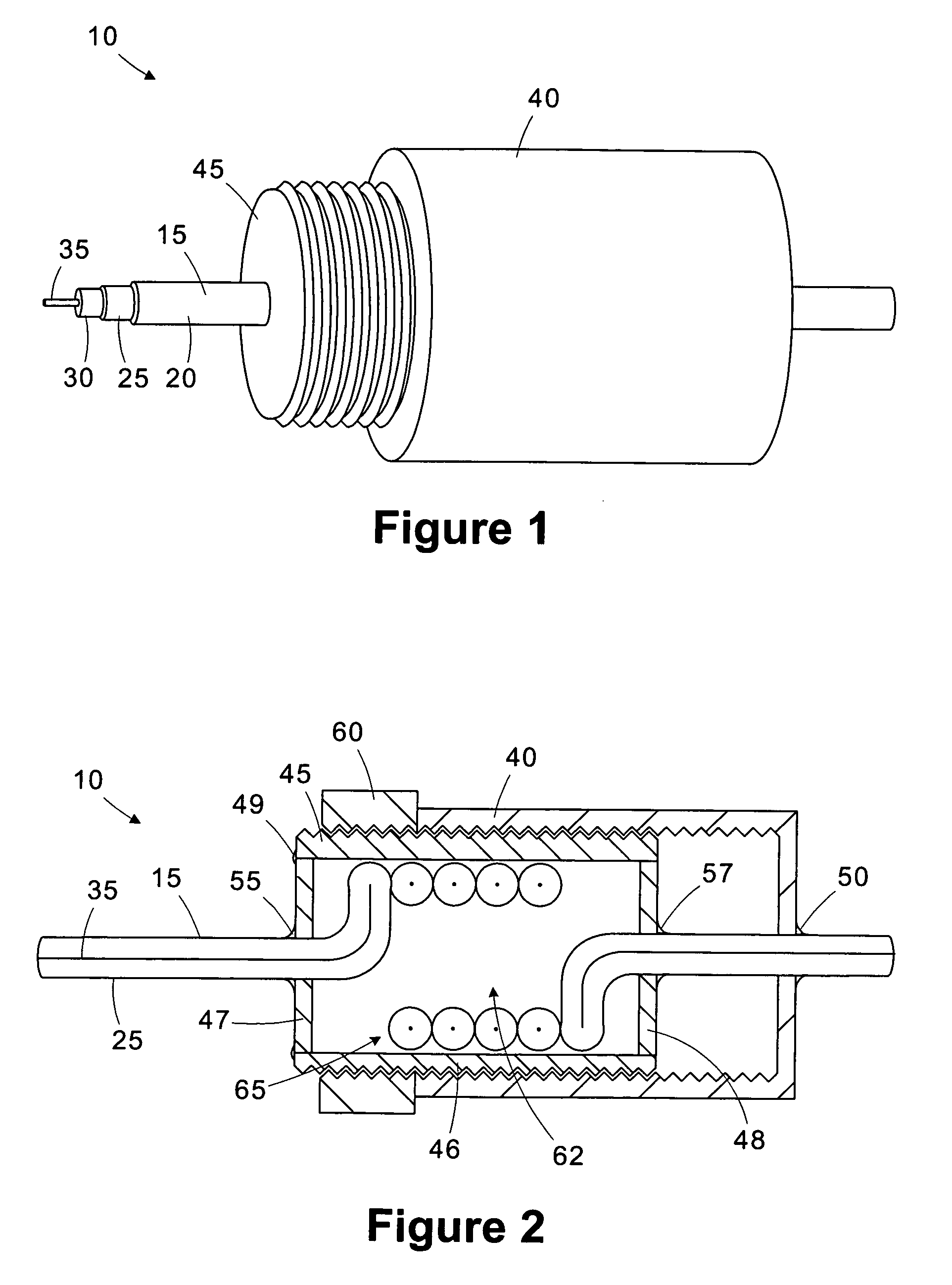
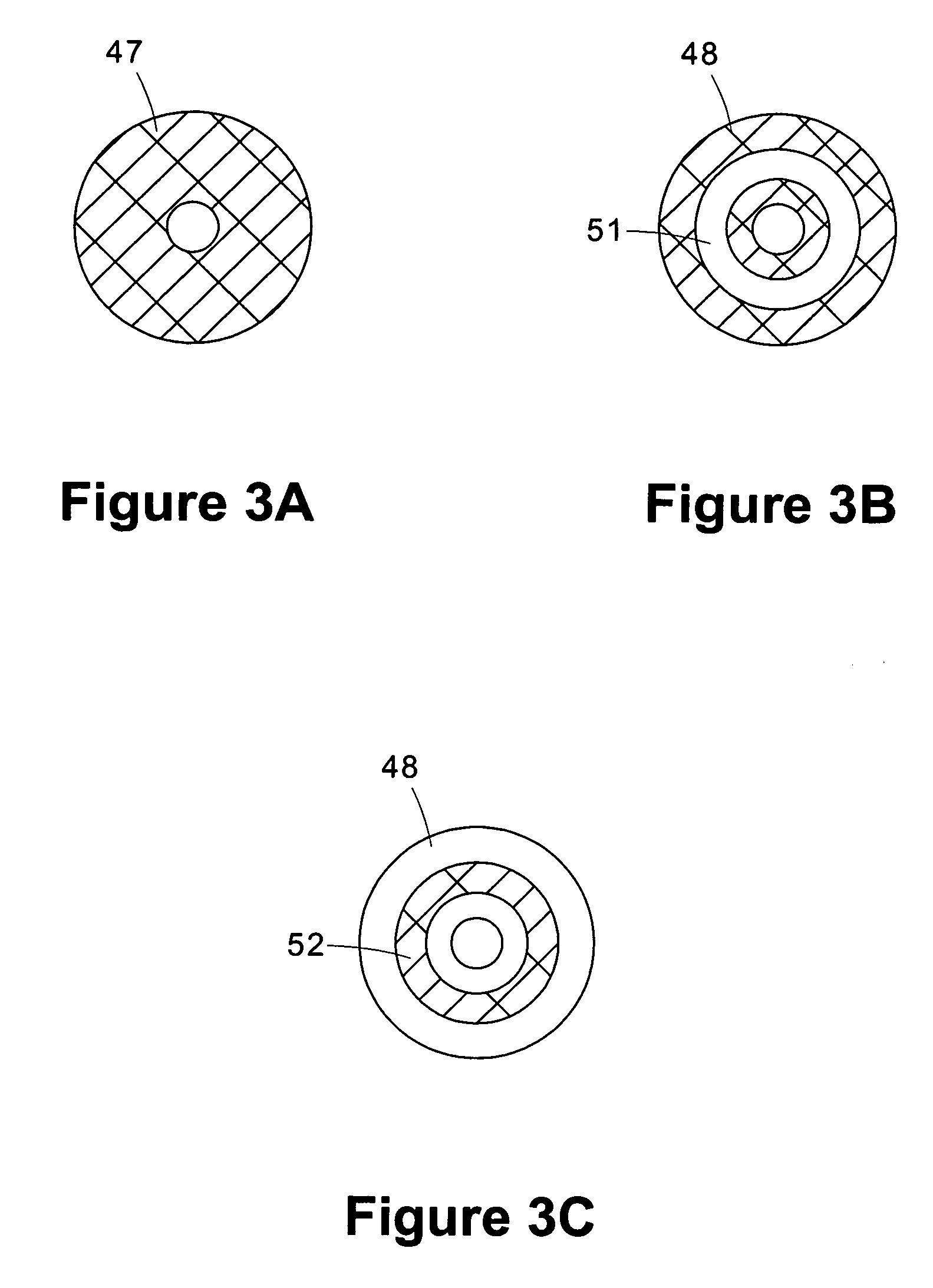
[0022] One or more specific embodiments of the present invention will be described below. It is specifically intended that the present invention not be limited to the embodiments and illustrations contained herein, but include modified forms of those embodiments including portions of the embodiments and combinations of elements of different embodiments as come within the scope of the following claims. It should be appreciated that in the development of any such actual implementation, as in any engineering or design project, numerous implementation-specific decisions must be made to achieve the developers' specific goals, such as compliance with system-related and business related constraints, which may vary from one implementation to another. Moreover, it should be appreciated that such a development effort might be complex and time consuming, but would nevertheless be a routine undertaking of design, fabrication, and manufacture for those of ordinary skill having the benefit of thi...


PUM


Abstract

A resonant cable trap for use with a shielded cable having an outer shield surrounding at least one inner conductor includes first and second members and a coil defined in the outer shield. The first member has a first conductive surface coupled to the shield. The second member has a second conductive surface coupled to the shield and is disposed to overlap at least a portion of the first member. The first and second conductive surfaces define a capacitor. The capacitor is coupled to the shield in parallel with the coil. A method for tuning the resonant cable trap includes adjusting the amount of overlap between the first and second members to tune the resonant frequency of the resonant cable trap.

Description

CROSS-REFERENCE TO RELATED APPLICATIONS [0001] Not applicable. STATEMENT REGARDING FEDERALLY SPONSORED RESEARCH OR DEVELOPMENT [0002] Not applicable BACKGROUND OF THE INVENTION [0003] The present invention relates generally to radio frequency traps and, more particularly, to a tunable resonant cable trap suitable for use with magnetic resonance imaging equipment. [0004] This section of this document is intended to introduce various aspects of art that may be related to various aspects of the present invention described and / or claimed below. This section provides background information to facilitate a better understanding of the various aspects of the present invention. It should be understood that the statements in this section of this document are to be read in this light, and not as admissions of prior art. [0005] Electrical conductors used for transmitting signals susceptible to external electromagnetic noise often employ a center conductor surrounded by a conductive shield. The ...

Claims


Application Information

Patent Timeline
IPC IPC(8): H03H7/01
CPCH01F21/10H01R4/02G01R33/3685H03H2001/0092H01R9/05
Inventor WYNN, TRACY ALLYNMOLYNEAUX, DAVID A.
Owner INVIVO CORP
Why Eureka
Eureka Blog
Learn More