Machine tool

a technology of machine tools and fixing methods, which is applied in the direction of manufacturing tools, metal-working machine components, attachable milling devices, etc., can solve the problems of affecting the machining accuracy the size increase of the entire machine, and the inability of the center portion of the workpiece to be fixed

Inactive Publication Date: 2006-12-28
DMG MORI CO LTD
View PDF5 Cites 51 Cited by
  • Summary
  • Abstract
  • Description
  • Claims
  • Application Information

AI Technical Summary

Benefits of technology

[0008] Moreover, in the above-described machining center, an outer periphery of the machine main body is generally surrounded and shielded by a cover in order to prevent chips and coolant from scattering out of the machine during the machining.
[0046] In this embodiment, each of the curtain plates is composed of the upper plate supported by the stick member and the lower plate supported by the upper plate to be movable in the up / down direction. Therefore, the lower plates relatively move in an upward direction, so that with a simple structure, it is possible to automatically and surely shield the openings above a long workpiece in a shape with different height positions.

Problems solved by technology

Here, if a table on the bed is moved in the same direction as the movement direction of the column from the viewpoint of realizing higher-speed movement of the spindle (see the aforesaid patent document 2), the bed has to be long enough to correspond to an amount of the movement of the table, which poses a problem of size increase of the entire machine.
Further, in the above-described conventional machine tool, when a wide and long workpiece with a size covering substantially the whole area of a machining table is to be machined, only an outer periphery of the workpiece is fixed and thus a center portion of the workpiece is not fully fixed, which gives rise to a concern that this workpiece fixing method may give an adverse effect to machining accuracy in this center portion.
However, in a machine tool for machining a relatively large and long workpiece, if the structure that a cover shields an outer periphery of a machine main body as in the above-described conventional machine tool is adopted, the cover needs to be large since the area to be shielded is large, which poses a problem of cost increase.

Method used


Image

  • Machine tool
  • Machine tool
  • Machine tool

Examples


second embodiment

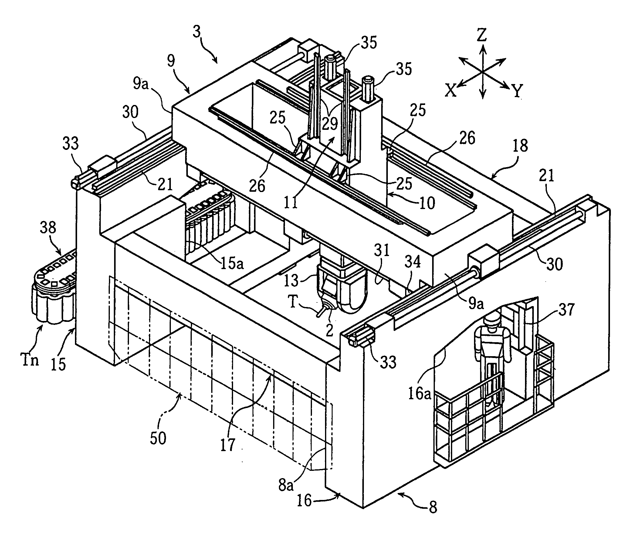
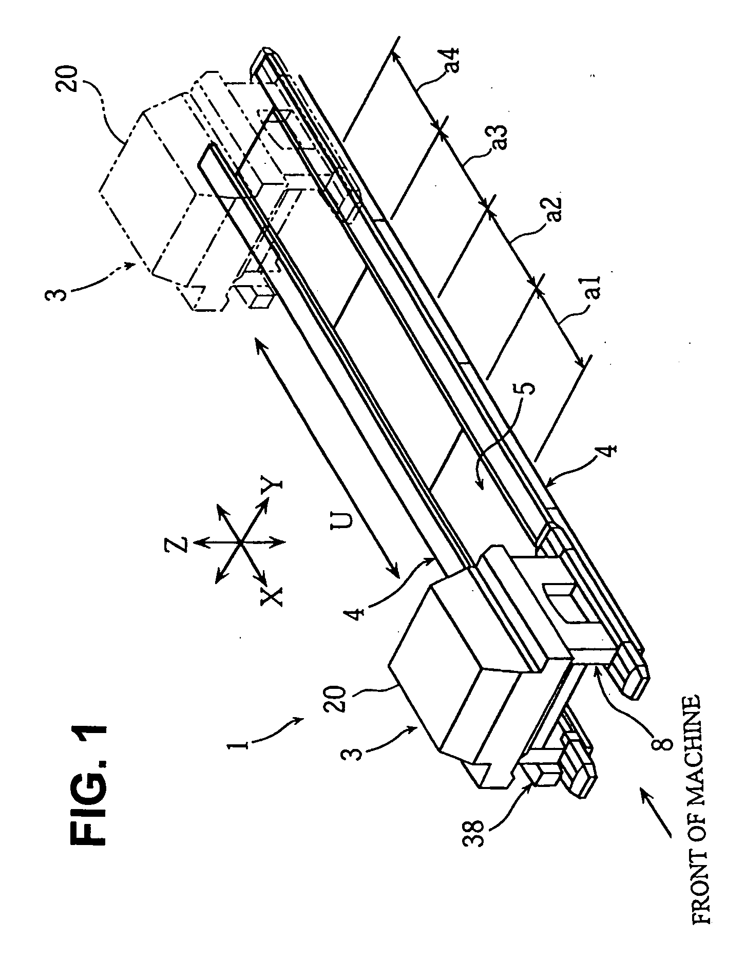
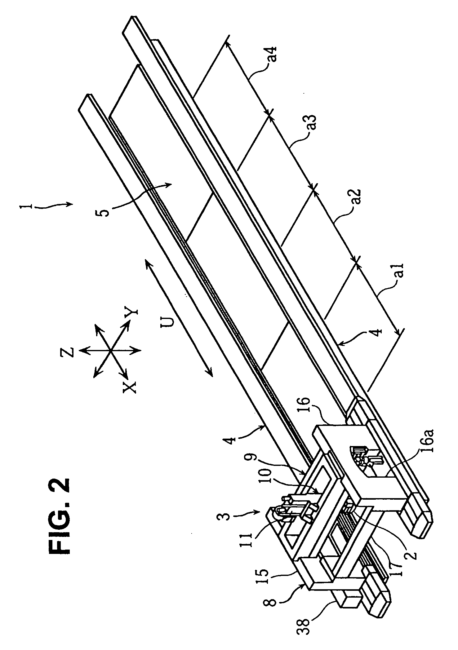
[0110]FIG. 16 is a perspective view to describe a horizontal machining center according to the present invention.

[0111] A horizontal machining center 151 of this embodiment includes: a machining unit 153 by which a spindle 152 with a tool T attached thereto is supported to be relatively movable in X-axis, Y-axis, and Z-axis directions; a bed 154 by which the machining unit 153 is supported to be movable in a U-axis direction (an arrangement direction of machining areas) parallel to the X-axis direction; and a machining table 155 disposed on a side of the bed 154 to be parallel thereto. Incidentally, the machining table 155 can be disposed on a wide bed.

[0112] The machining unit 153 includes: a rectangular column 60 in which, when seen in the U-axis direction from a front side of the machine, front and rear column main bodies 155a, 155b disposed on the bed 154 are integrally coupled by upper and lower cross frames 157, 158; a rectangular cross rail 61 disposed in a space surrounded ...

third embodiment

[0115]FIG. 17 is a view to describe shielding members according to the present invention. The same reference numerals as those in FIG. 5 denote the same or corresponding portions.

[0116] A shielding mechanism 160 of this embodiment is structured such that three cylinder mechanisms 57 are arranged between left and right column main bodies 15, 16 at predetermined intervals, piston rods 58 of the cylinder mechanisms 57 are fixed to stick members 161, and a large number of curtain plates 162 are hung from and supported by the stick members 161 to be vertically movable. Note that each of the cylinder mechanisms 57 is fixedly attached to the cross frame 17 or 18.

[0117] The cylinder mechanisms 57 independently drive the curtain plates 162 via the respective stick members 161 to move up / down between a closing position and an opening position. When the stick members 161 move down so that the curtain plates 162 abut on a workpiece, the curtain plates 162 stop at this abutting position. In thi...


PUM

PropertyMeasurementUnit
widthaaaaaaaaaa
lengthaaaaaaaaaa
shapeaaaaaaaaaa

Abstract

The present invention provides a machine tool realizing high-speed movement of a spindle and thus reducing the machining time without any increase in size of the whole machine. A machining unit 3 by which a spindle 2 with a tool T attached thereto is supported to be relatively movable in X-axis, Y-axis, and Z-axis directions is mounted on a long bed 4 having a plurality of machining areas a1 to a4 arranged in one direction, and the machining unit 3 is movable in the arrangement direction of the machining areas.

Description

BACKGROUND OF THE INVENTION [0001] 1. Field of the Invention [0002] The present invention relates to a machine tool in which a spindle with a tool attached thereto is supported to be relatively movable in X-axis, Y-axis, and Z-axis directions, and more particularly, to a structure of a machine tool capable of machining a wide and long workpiece efficiently. [0003] 2. Description of the Related Art [0004] As a gantry-type machining center for machining a relatively long workpiece, there is one described in, for example, Japanese Patent Application Laid-open No. 2001-219325 (patent document 1) or Japanese Patent Application Laid-open No. Hei 8-150534 (patent document 2). The one described in the patent document 1 is structured such that a gate-shaped column 7 is disposed on a long bed 2 to be movable in an X-axis direction, a saddle 25 is disposed on a front face of a cross rail 7c of a column 7 to be movable in a Y-axis direction, a ram 30 is disposed on the saddle 25 to be movable i...

Claims


Application Information

Patent Timeline
Patent Type & Authority Applications(United States)
IPC IPC(8): B23Q1/01
CPCB23Q1/012B23Q1/626B23Q3/069Y10T409/307728Y10T409/30952Y10T409/308288Y10T409/30392Y10S83/939
Inventor TANOUE, SHINNFUJIWARA, RYUICHIKOTAKA, TOSHIAKIISHIGAKI, HIKARU
Owner DMG MORI CO LTD
Why Eureka
Try Eureka