Bi-polar rechargeable electrochemical battery

Inactive Publication Date: 2006-12-28
G4 SYNERGETICS INC
View PDF92 Cites 60 Cited by
  • Summary
  • Abstract
  • Description
  • Claims
  • Application Information

AI Technical Summary

Benefits of technology

[0006] It is therefore an object of this invention to provide a bi-polar battery with improved sealing of electrolyte between adjacent bi-polar electrode units.

Problems solved by technology

The wound cell and prismatic cell structures suffer from high electrical resistances due to their electrical paths having to cross multiple connections and cover significantly long distances to cover the complete circuit from one cell to the next in a series arrangement.
However, if the current collectors contacted each other or if the common electrolyte of any two adjacent BPUs is shared with any additional BPU, the voltage and energy of the battery would fade (i.e., discharge) quickly to zero.

Method used


Image

  • Bi-polar rechargeable electrochemical battery
  • Bi-polar rechargeable electrochemical battery
  • Bi-polar rechargeable electrochemical battery

Examples


Embodiment Construction

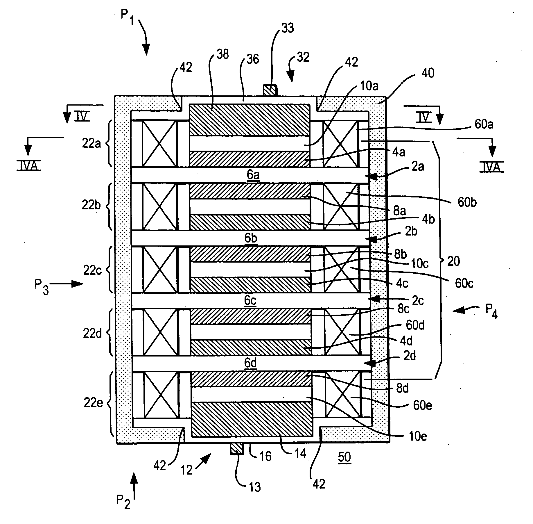
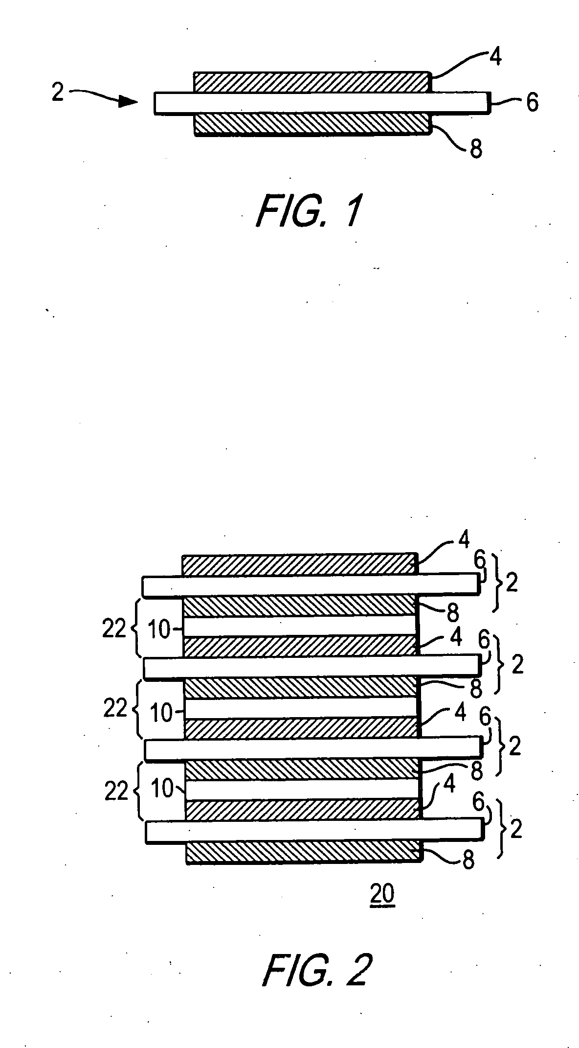
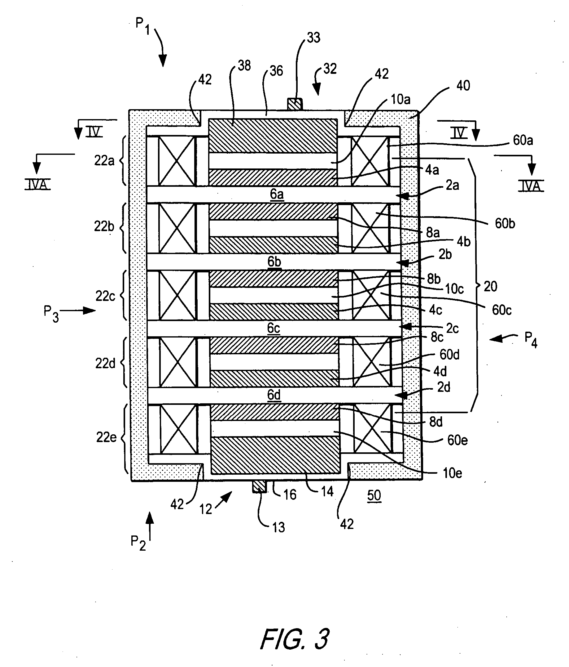
[0034] The invention provides a bi-polar battery having a positive mono-polar unit (MPU) terminal, a negative MPU terminal, and at least one bi-polar unit (BPU) arranged substantially vertically therebetween. Each BTU includes an electrode layer (e.g., a conductive substrate) having two sides. A positive active material is formed or positioned on the first side of the electrode layer, and a negative material is formed or positioned on the second side of the electrode layer. The bi-polar battery of this invention also includes an electrolyte layer having an electrolyte between each adjacent electrode unit (i.e., between each MPU and adjacent BPU, and between each BPU and adjacent BPU) and a barrier that electrically isolates the adjacent electrode units between which the electrolyte layer is positioned. Additionally, the bi-polar battery of this invention includes a gasket positioned substantially about each electrolyte layer for sealing the electrolyte of the electrolyte layer betwe...


PUM


Abstract

A bi-polar battery has a positive electrode unit, a negative electrode unit, at least one bi-polar electrode unit stacked therebetween, an electrolyte layer separating each adjacent electrode unit, and a gasket positioned about each electrolyte layer for creating a seal about the electrolyte layer in conjunction with the electrode units adjacent thereto. The bi-polar battery also includes a wrapper for maintaining the seals created by the gaskets.

Description

[0001] This application claims the benefit of U.S. Provisional Patent Application No. 60 / 677,512, filed May 3, 2005, which is hereby incorporated by reference herein in its entirety.FIELD OF THE INVENTION [0002] This invention relates generally to batteries and, more particularly, to bi-polar batteries with improved sealing. BACKGROUND OF THE INVENTION [0003] Bi-polar batteries are able to provide an increased discharge rate and a higher voltage potential between its external connectors than standard wound or prismatic batteries, and are therefore in high demand for certain applications. Conventional batteries have been manufactured as either a wound cell battery that has only two electrodes or a standard prismatic cell battery that has many plate sets in parallel. In both of these types, the electrolyte can be shared everywhere within the battery. The wound cell and prismatic cell structures suffer from high electrical resistances due to their electrical paths having to cross multi...

Claims


Application Information

Patent Timeline
IPC IPC(8): H01M2/08H01M4/02H01M50/184H01M50/186
CPCH01M2/08H01M10/0413H01M10/0418H01M10/0468Y10T29/4911H01M10/0486H01M10/345Y02E60/124H01M10/0477Y02E60/10Y02P70/50H01M50/184H01M50/186
Inventor OGG, RANDYSMITH, DAVID RUSSELLPARK, DAVID FRASER
Owner G4 SYNERGETICS INC
Why Eureka
Try Eureka