Contact image sensor and image reader

a contact image sensor and image reader technology, applied in the field of image readers, can solve the problems of general difficulty in realizing an accurate orthogonal relationship between the axial direction of the guide shaft and the longitudinal direction of the contact image sensor, and achieve the effect of low cos

Active Publication Date: 2007-01-04
BROTHER KOGYO KK
View PDF3 Cites 29 Cited by
  • Summary
  • Abstract
  • Description
  • Claims
  • Application Information

AI Technical Summary

Benefits of technology

[0017] An object of the present invention is to provide an image reader in which accurate orthogonality of a longitudinal direction of a sensor (con

Problems solved by technology

Thus, as described above, it is generally difficult to realize an accurately orthogonal relationship be

Method used


Image

  • Contact image sensor and image reader
  • Contact image sensor and image reader
  • Contact image sensor and image reader

Examples


first embodiment

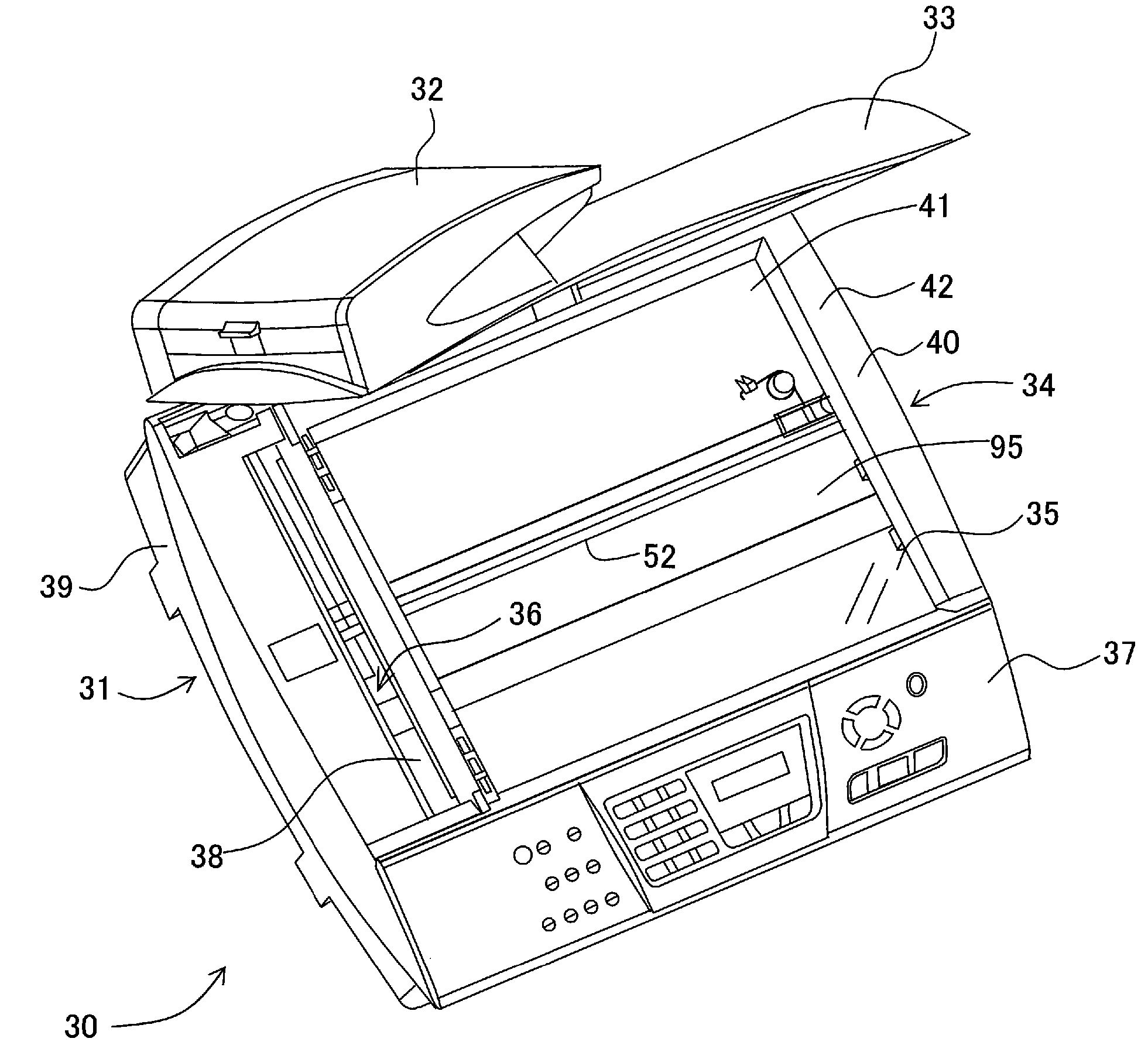
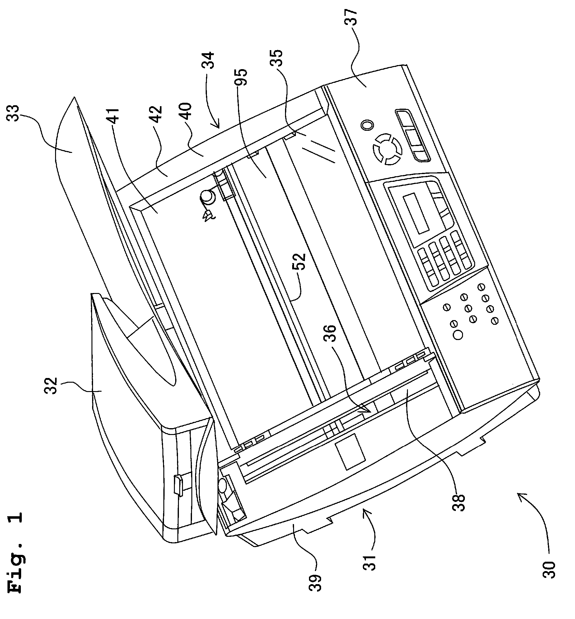
[0080]FIG. 1 is an external perspective view of an the image reader 30 according to a first embodiment of the present invention.

[0081] This image reader 30 may be used, for example, as a scanner unit of a multi function device (MFD) which is integrally equipped with a printer function and a scanner function, or as an image reading unit of a copier. In the present invention, the printer function is an arbitrary mechanism, and the image reader 30 may be constructed as a flatbed scanner (FBS) having the scanner function only.

[0082] As shown in FIG. 1, this image reader 30 has a reading platform 31 (document placing / reading platform) which functions as an FBS, and a document pressing cover 33 is mounted onto the reading platform 31 in an openable / closable manner. This document pressing cover 33 has an auto document feeder (ADF) 32. The reading platform 31 has a body frame 34 (casing) of substantially rectangular parallelepiped shape, a contact glass plate (light transmitting plate) 35...

second embodiment

[0120] A second embodiment of the present invention will now be explained.

[0121]FIG. 9 is an enlarged perspective view of principal portions of an image reading unit of an image reader according to a second embodiment of the present invention.

[0122] The image reading unit according to this embodiment differs from the image reading unit according to the above-described first embodiment in that, although in the first embodiment, the guide shaft 52 supports the CIS unit 50 in a slidable manner in the short direction and the guide shaft 52 is elastically urged upward by the coil springs 63, whereas in the second embodiment, the guide shaft 52 passes through a CIS unit 140 in a state in which the CIS unit 140 is movable in the vertical direction (the direction orthogonal to both the longitudinal direction and the short direction); and slide rollers 141 and 142 as sliding member provided on the CIS unit 140 elastically urge the CIS unit 140 upward and aid smooth sliding of CIS unit 10. ...


PUM


Abstract

An image reader includes a casing, a contact glass plate, a contact image sensor, and a sliding mechanism; wherein the contact image sensor has a housing, a light source attached to the housing so as to face the contact glass plate, a plurality of light receiving elements attached to the housing so as to face the contact glass plate and aligned in parallel in a longitudinal direction of the housing, and a bearing formed integral to the housing at a position below a lower surface of the housing; and the sliding mechanism includes a guide shaft provided on the casing and extending in a short direction of the housing and inserted through the bearing, and an urging member elastically which urges the guide shaft toward the contact glass plate so that the housing is pressed against the contact glass plate.

Description

CROSS REFERENCE TO RELATED APPLICATIONS [0001] The present application claims priority from Japanese Patent Application No. 2005-192522, filed on Jun. 30, 2005, the disclosure of which is incorporated herein by reference in its entirety. BACKGROUND OF THE INVENTION [0002] 1. Field of the Invention [0003] The present invention relates to an image reader employed in an MFD (Multi Function Device), etc., and particularly relates to a structure of a contact image sensor which is incorporated in an image reader. [0004] 2. Description of the Related Art [0005] Conventionally, a CCD sensor or a contact image sensor (CIS) is used as a sensor of an image reader. A CCD sensor is constructed of a light source, a mirror, a lens, a CCD and the like. Image reading is performed by the light source illuminating light onto a document (original) and the CCD receiving the reflected light, and has a feature that a focal length is secured by using a plurality of mirrors to make the reflected light be co...

Claims


Application Information

Patent Timeline
IPC IPC(8): H04N1/04
CPCH04N1/1017H04N1/1026H04N2201/02402H04N1/193H04N1/103
Inventor OSAKABE, YOSHINORISATO, TATSUYASAKAKIBARA, AKIHIROOHAMA, TAKASHI
Owner BROTHER KOGYO KK
Why Eureka
Try Eureka