
Non-linear artificial ligament system

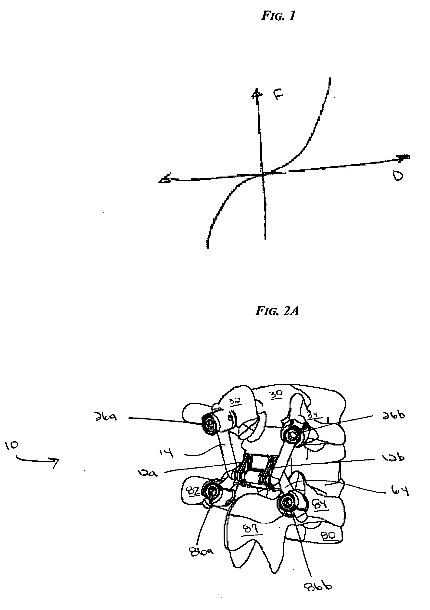
a ligament system and artificial technology, applied in the field of artificial ligament systems, can solve the problems of many artificial joint replacements, less motion, and extensive removal of ligaments surrounding the joint,

Active Publication Date: 2007-01-04
DEPUY SPINE INC (US)
View PDF15 Cites 137 Cited by
  • Summary
  • Abstract
  • Description
  • Claims
  • Application Information

AI Technical Summary

Benefits of technology

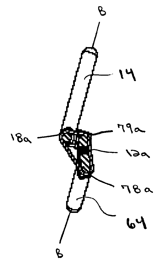
[0008] The first and second connection members also have a ligament seating region and a ligament contact region. The ligament seating region can have any configuration that can hold the artificial ligament in place, such as a groove or a post. The post can have a groove or a stop formed therein to receive the artificial ligament, as well as to prevent it from sliding off the post. While the connection members can have any number of ligament contact regions, in an exemplary embodiment the first connection member can have at least one ligament contact region and the second connection member can have at least two ligament contact regions. The ligament contact region can have a configuration that allows the artificial ligament to slide thereover, and in an exemplary embodiment the ligament contact region is a smooth or curved surface. Alternatively, the ligament contact region can be a pulley or a pivot point. The ligament contact region generally has a surface area that is large enough to allow for contact with the artificial ligament, and, when the system includes two connection members, the surface area of the ligament contact region of the second connection member can be greater than that of the first connection member. This surface area differential results in the second connection member having at least two ligament contact regions, which are preferably located at opposed edges of the ligament seating region, and helps the artificial ligament exhibit a non-linear force displacement relationship.

Problems solved by technology

While current artificial ligaments may relieve pain, they typically provide less motion than natural ligaments.
Furthermore, many artificial joint replacements, such as spine, knee, hip, and shoulder, require extensive removal of the ligaments surrounding the joint.

Method used


Image

  • Non-linear artificial ligament system
  • Non-linear artificial ligament system
  • Non-linear artificial ligament system

Examples


Embodiment Construction

[0030] Certain exemplary embodiments will now be described to provide an overall understanding of the principles of the structure, function, manufacture, and use of the devices and methods disclosed herein. One or more examples of these embodiments are illustrated in the accompanying drawings. Those of ordinary skill in the art will understand that the devices and methods specifically described herein and illustrated in the accompanying drawings are non-limiting exemplary embodiments and that the scope of the present invention is defined solely by the claims. The features illustrated or described in connection with one exemplary embodiment may be combined with the features of other embodiments. Such modifications and variations are intended to be included within the scope of the present invention.

[0031] Disclosed herein are various methods and devices for ligament replacement in a body, and in particular, for replacement of ligaments in the spine. In one exemplary embodiment, a lig...


PUM


Abstract

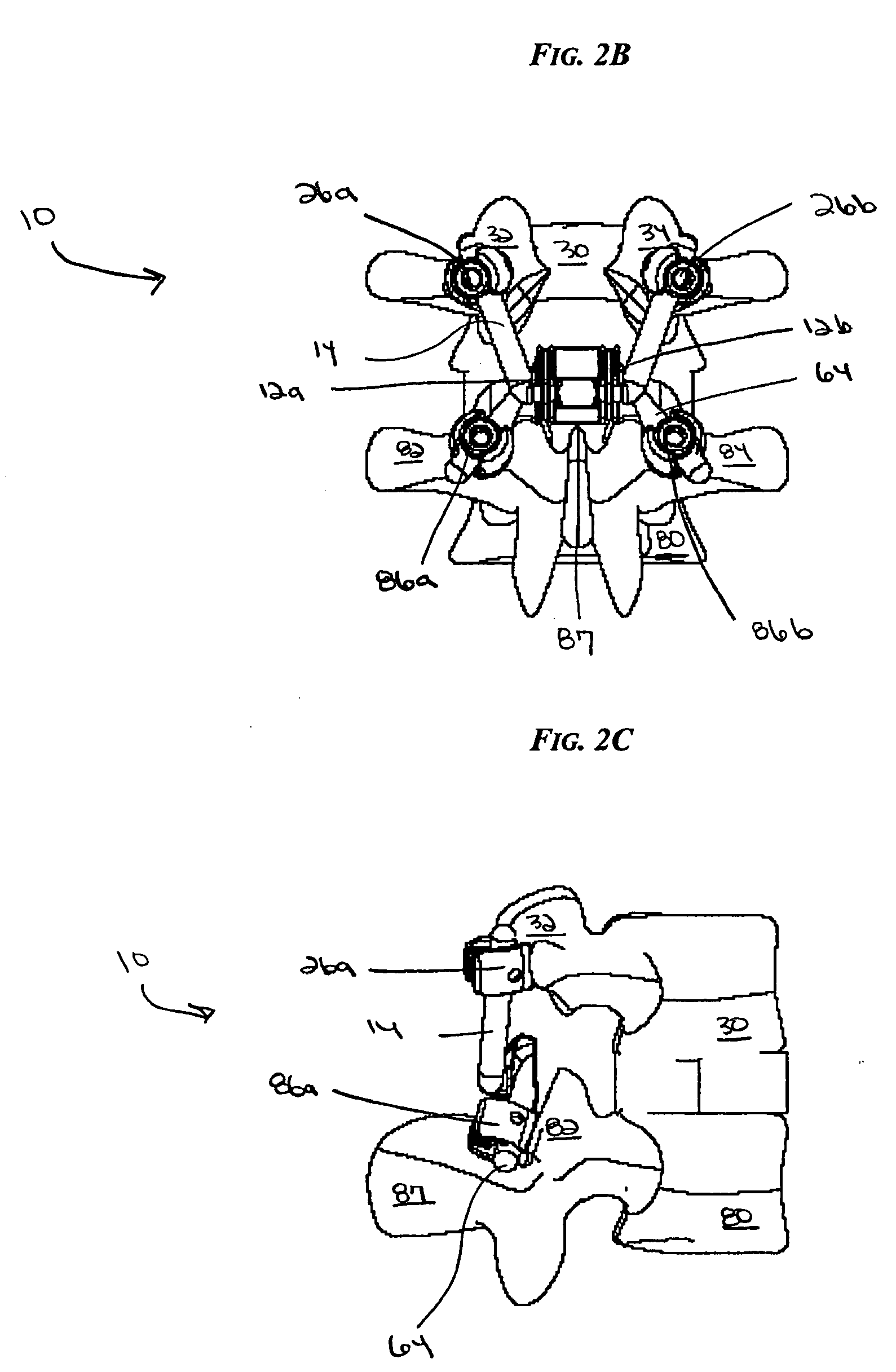
Various methods and devices for ligament replacement in the human body, and in particular, the spine are provided. In an exemplary embodiment, a ligament replacement system is provided that has an artificial ligament configured in the form of a closed loop. The artificial ligament is adapted to be coupled between the ligament seating regions of first and second connection members in a connection geometry that results in the artificial ligament having a large motion with a non-linear relationship between the force and displacement, similar to that of a natural ligament.

Description

BACKGROUND OF THE INVENTION [0001] Ligaments are strong bands of fibrous tissue that can connect bones, such as the bones of the spinal column. There are two primary ligament systems in the spine, the intrasegmental system and the intersegmental system. The intrasegmental system holds the individual vertebrae together, and includes the ligamentum flavum, interspinous and intertransverse ligaments. The intersegmental system extends along the length of the vertebral column, and includes the anterior and posterior longitudinal ligaments, and the supraspinous ligaments. [0002] Both of these ligament systems work in conjunction with the facet joints to provide structural stability and / or prevent excessive movement of the spinal column. Particularly, the ligamentous structures exhibit a non-linear relationship between motion and force, where initially little force is required for motion, and a greater additional force is required at larger motion. Further, these structures have properties...

Claims


Application Information

Patent Timeline
Patent Type & Authority Applications(United States)
IPC IPC(8): A61F2/08A61B17/70
CPCA61B17/7022A61B17/7043A61F2/08A61F2/0811A61F2002/0888A61F2002/0852A61F2002/0864A61F2002/087A61F2002/0829
Inventor KWAK, SEUNGKYU DANIEL
Owner DEPUY SPINE INC (US)
Learn More