

Modular housing including support rail connecting means
a technology of supporting rails and modules, applied in the direction of electrical apparatus casings/cabinets/drawers, substation/switching arrangement details, support structure mounting, etc., can solve the problems of relatively complicated operation and design, and achieve the effect of convenient reaching
- Summary
- Abstract
- Description
- Claims
- Application Information
AI Technical Summary
Benefits of technology
Problems solved by technology
Method used
Image

Examples
Embodiment Construction
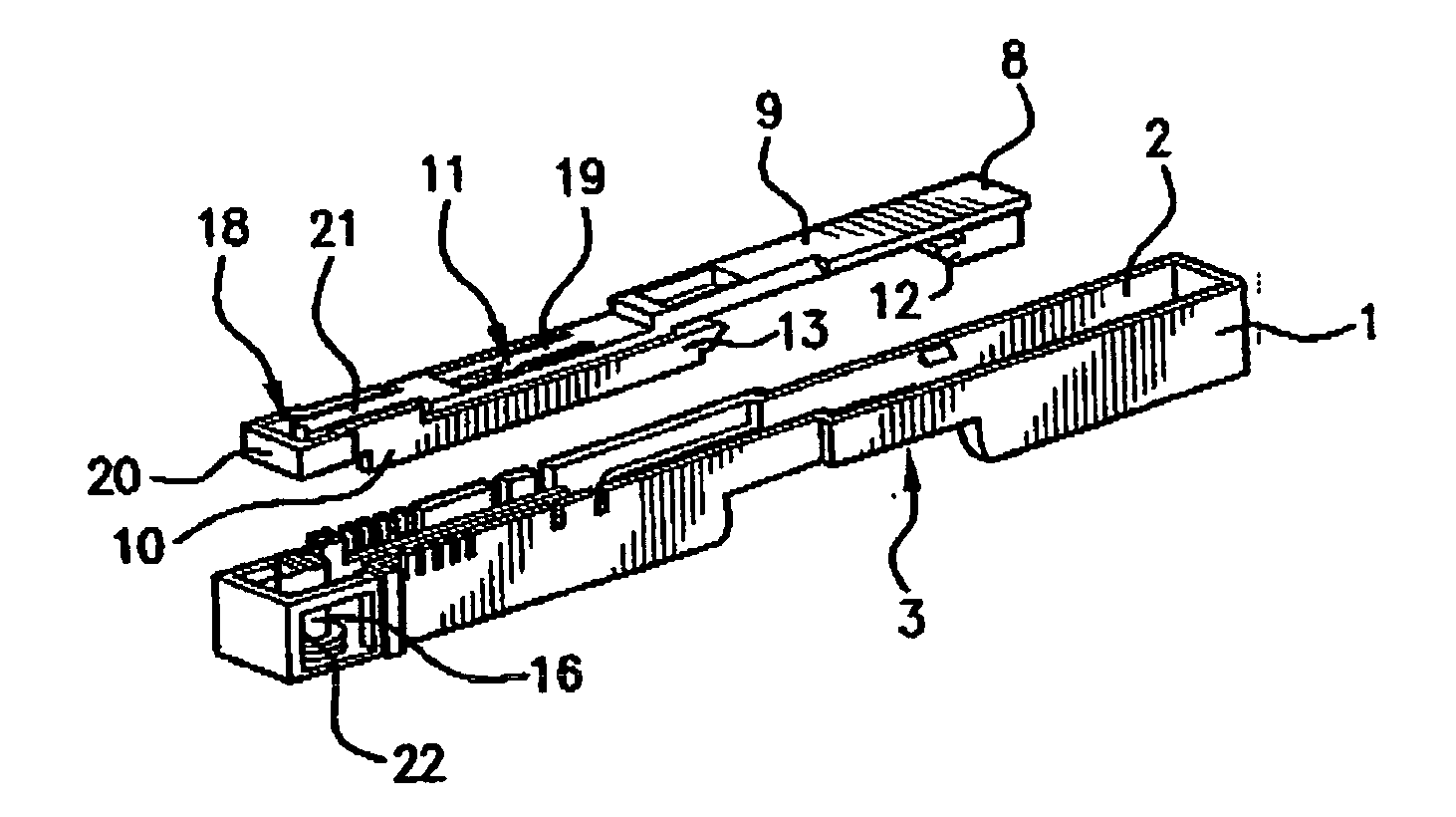
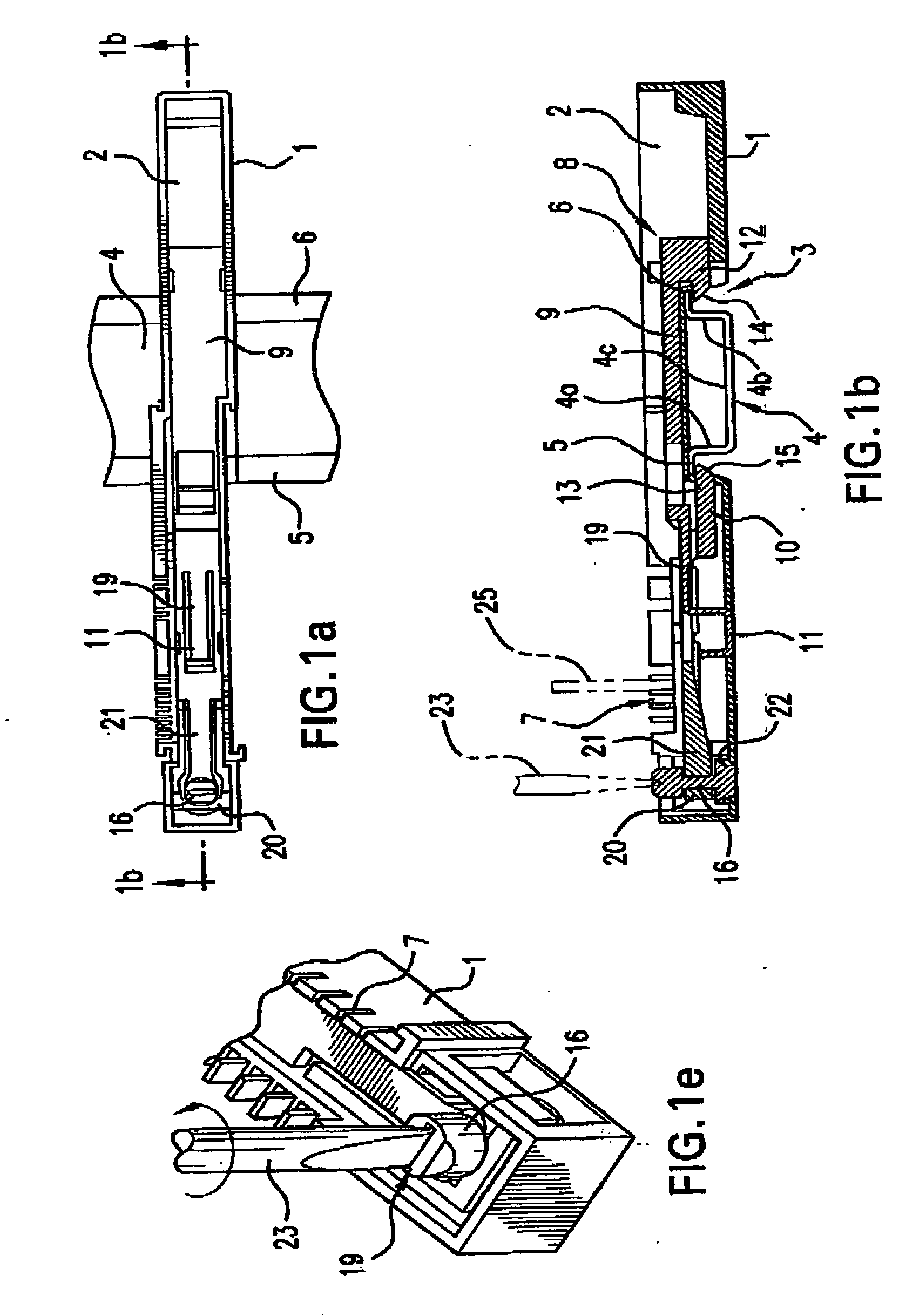
[0027] Referring first more particularly to FIGS. 1a-1e, the module connecting means of the present invention includes a generally rectangular frame-like housing 1 containing an upper chamber 2, the bottom wall of the housing containing a recess 3 for transversely receiving the stationary mounting rail 4. As is known in the art, the mounting rail 4 has a generally U-shaped or hat-shaped cross-sectional configuration including a pair of vertical leg portions 4a and 4b that are joined at their lower ends by a horizontal bridging portion 4c. At their upper extremities, the vertical leg portions are provided with laterally outwardly extending horizontal flange portions 5 and 6, respectively.
[0028] Mounted within the longitudinally extending chamber 2 are locking means 8 that serve to lock the housing 1 to the support rail 4. More particularly, the locking means 8 includes a pair of parallel superimposed slidably connected locking slide members 9 and 10. The upper slide member 9 extends...
PUM
 Abstract
Description
Claims
Application Information