Modeling of a microphone

a technology of modeling and microphones, applied in the field of signal modeling, can solve problems such as mechanical design changes, reduced sound quality detected by the microphone, and inability to rotate the desired directivity pattern

Active Publication Date: 2007-01-11
AKG ACOUSTICS
View PDF7 Cites 44 Cited by
  • Summary
  • Abstract
  • Description
  • Claims
  • Application Information

AI Technical Summary

Problems solved by technology

A directivity pattern may deviate from ideal directional behavior of sound transmitted from an audio source, which may reduce the sound quality detected by the microphone.
However, such models may require mechanical design changes and the desired directivity pattern may not be rotationally symmetric.

Method used


Image

  • Modeling of a microphone
  • Modeling of a microphone
  • Modeling of a microphone

Examples


Embodiment Construction

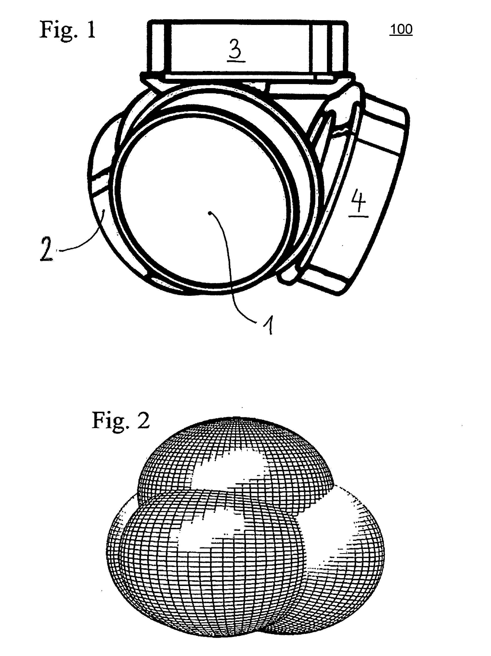
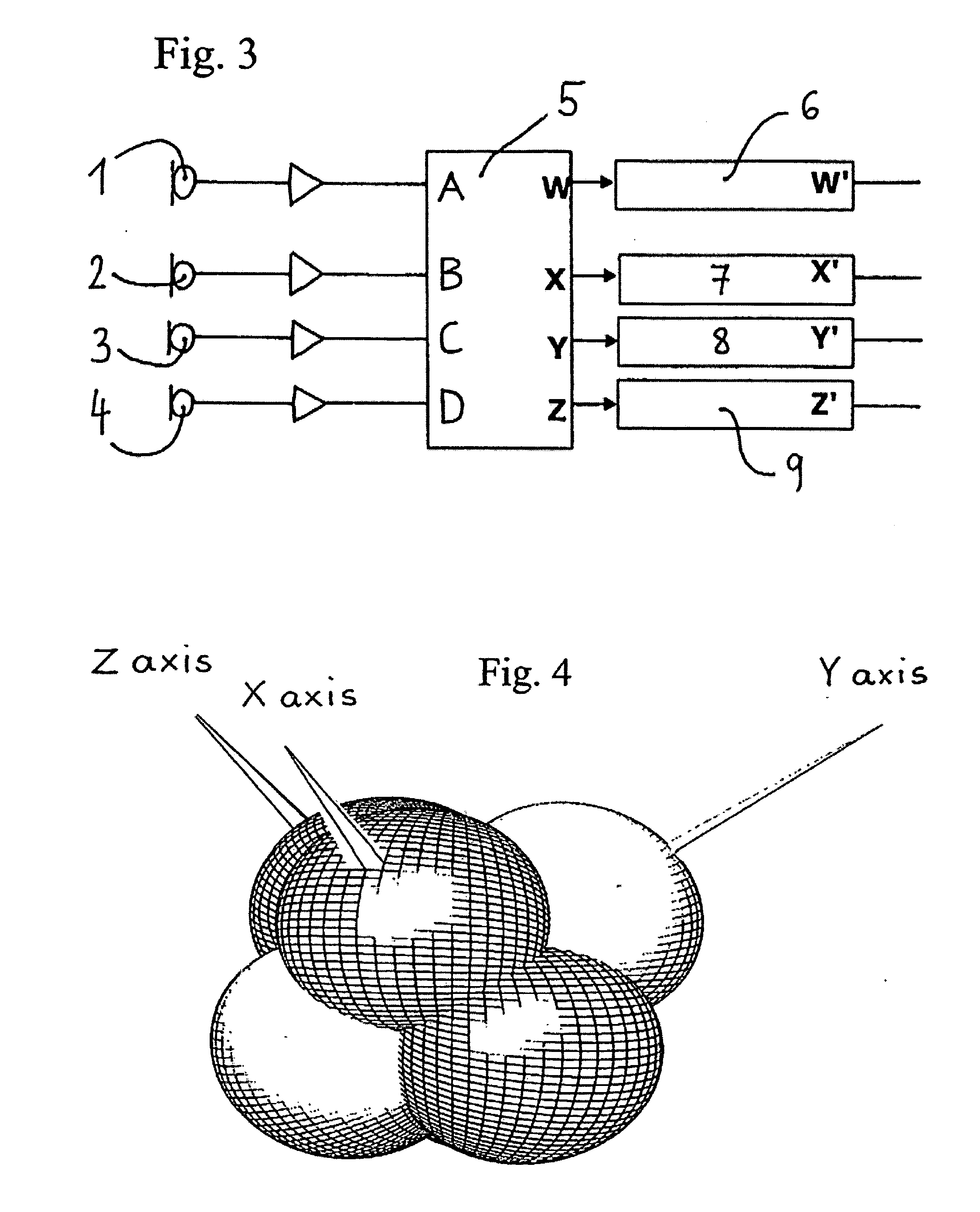
[0021]FIG. 1 is a diagram of a microphone 100. The microphone 100 may combine a device that converts sound into analog or digital signals, that may be sent into a second device, such as an amplifier, a recorder, or a broadcast transmitter. The microphone 100 of FIG. 1 is shown with four capsules 1, 2, 3, and 4 arranged on a substantially spherical surface. In this system, the membranes of the capsules are almost parallel to the sides of a tetrahedron, which comprises a four-sided polygon in the shape of a pyramid. As shown, there is a capsule located on each of the four faces. In other systems, a microphone may have more or less capsules positioned in other arrangements. A capsule includes a transducer, which contains the structure that converts acoustic sound waves into analog or digital signals. In FIG. 1, the microphone 100 has four pressure-gradient capsules arranged on the surface. The number and the arrangement of capsules may affect the directivity pattern of the microphone. ...


PUM


Abstract

A system that models a microphone may include capsules that receive individual signals. The signals may be combined and modified based on a weighting factor. Directivity patterns of a converted signal may be modified or controlled based on the weighting of the signals.

Description

BACKGROUND OF THE INVENTION [0001] 1. Priority Claim [0002] This application claims the benefit of priority from European Application No. 054501119, filed Jun. 23, 2005, which is incorporated by reference. [0003] 2. Technical Field [0004] This application relates to the modeling of signals received by devices that convert sound waves into analog or digital signals. Related Art [0005] A microphone may include individual capsules that receive audio signals. Each capsule receives an audio signal. The capsules may be positioned in directivity patterns. A microphone may receive signals in an ominidirectional, cardioid, or figure-eight directivity pattern. [0006] A directivity pattern may deviate from ideal directional behavior of sound transmitted from an audio source, which may reduce the sound quality detected by the microphone. Some systems attempt to model deviations by combining or modifying directivity patterns. However, such models may require mechanical design changes and the des...

Claims


Application Information

Patent Timeline
Patent Type & Authority Applications(United States)
IPC IPC(8): H04R3/00
CPCH04R1/326H04R5/027H04S2420/11H04S3/00H04S2400/15H04R2410/01
Inventor REINING, FRIEDRICHBREITSCHADEL, HANNES
Owner AKG ACOUSTICS
Why Eureka
Try Eureka