Fuse-electrode electrosurgical apparatus

a technology of electrosurgical equipment and fuse electrode, which is applied in the field of electrosurgical equipment, can solve the problems of affecting the operation efficiency of the electrosurgical equipment, affecting the operation efficiency of the surgical equipment,

Inactive Publication Date: 2007-01-11
ARTHROCARE
View PDF98 Cites 88 Cited by
  • Summary
  • Abstract
  • Description
  • Claims
  • Application Information

AI Technical Summary

Benefits of technology

[0013] Advantageously, with the present instrument and method, a target tissue may be treated with reduced risk and consequences of a random instrument failure since the instrument is adapted to fail upon expiration of a predetermined amount of use. In various embodiments, failure is intentional due to a planned break in the electrode to incapacitate the instrument and disclosed herein.

Problems solved by technology

However, while monitoring the power supply is feasible to track the time that the tissue is exposed to current, merely monitoring the power does not indicate to the operator the extent of erosion and wear occurring on the electrodes.
In this regard the applicant has discovered that as the instrument is used, the active electrode erode and wear and are likely to break.
Further, depending on the material used, the dimensions of the active electrode, the type of conductive fluid used, the location of the connection to the power supply and the voltage applied to the electrodes, erosion may occur to the extent where the electrodes undesirably breaks causing bits of fragments to become lodged in the tissue.
Thus, while it is possible to monitor the power to prevent over-exposure of the tissue to current, it is a problem to decide when to stop use of the instrument to avoid the undesirable consequences of erosion and wear on the electrodes and or a break on the electrodes.
A problem with this approach is that because the electrodes are almost invisible to an unaided eye, it very difficult to visually determine erosion and wear.
A further practical problem is that during the exigencies of a surgical procedure, a practitioner may overlook the need to periodically check the electrodes for erosion wear in time to stop using the instrument before wear becomes a problem and or the electrode breaks.

Method used


Image

  • Fuse-electrode electrosurgical apparatus
  • Fuse-electrode electrosurgical apparatus
  • Fuse-electrode electrosurgical apparatus

Examples


Embodiment Construction

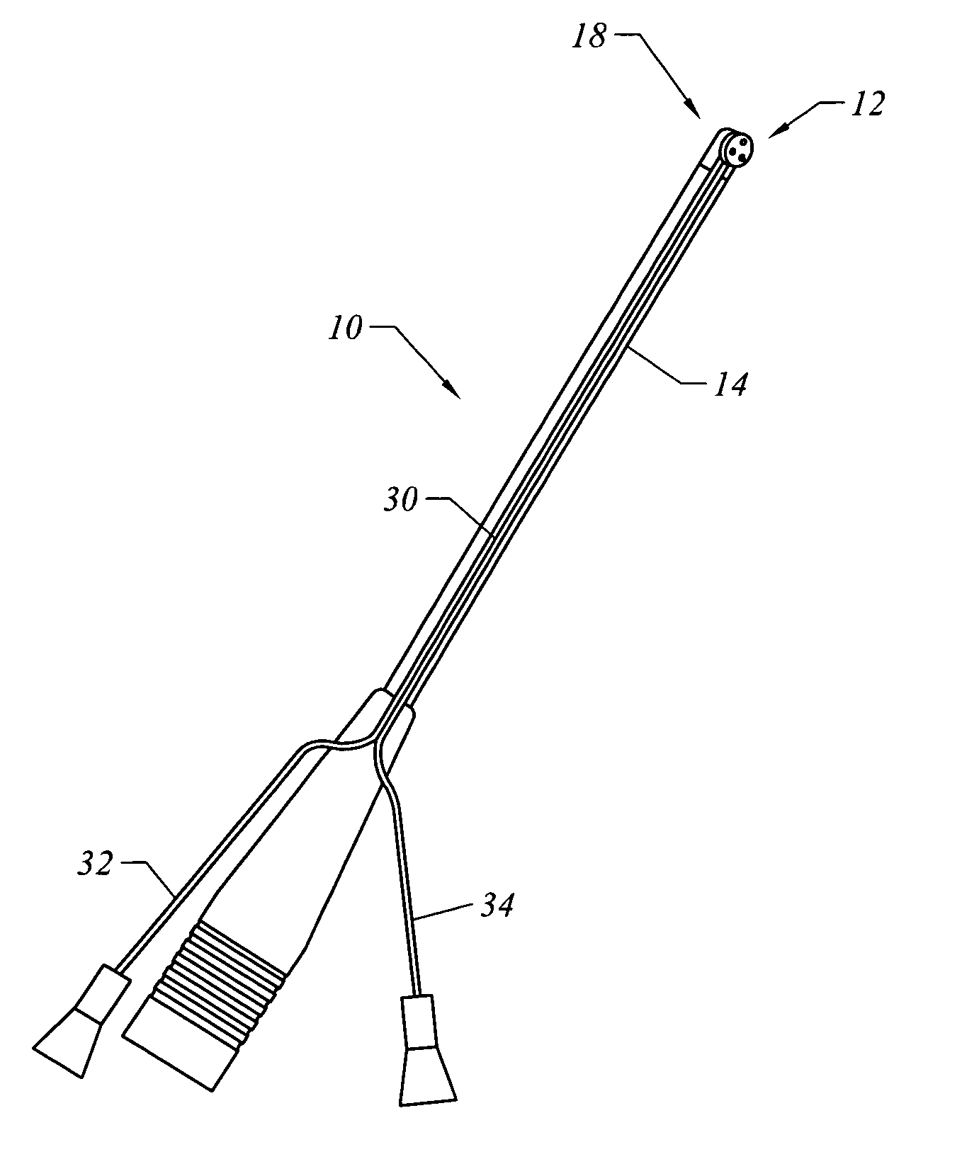
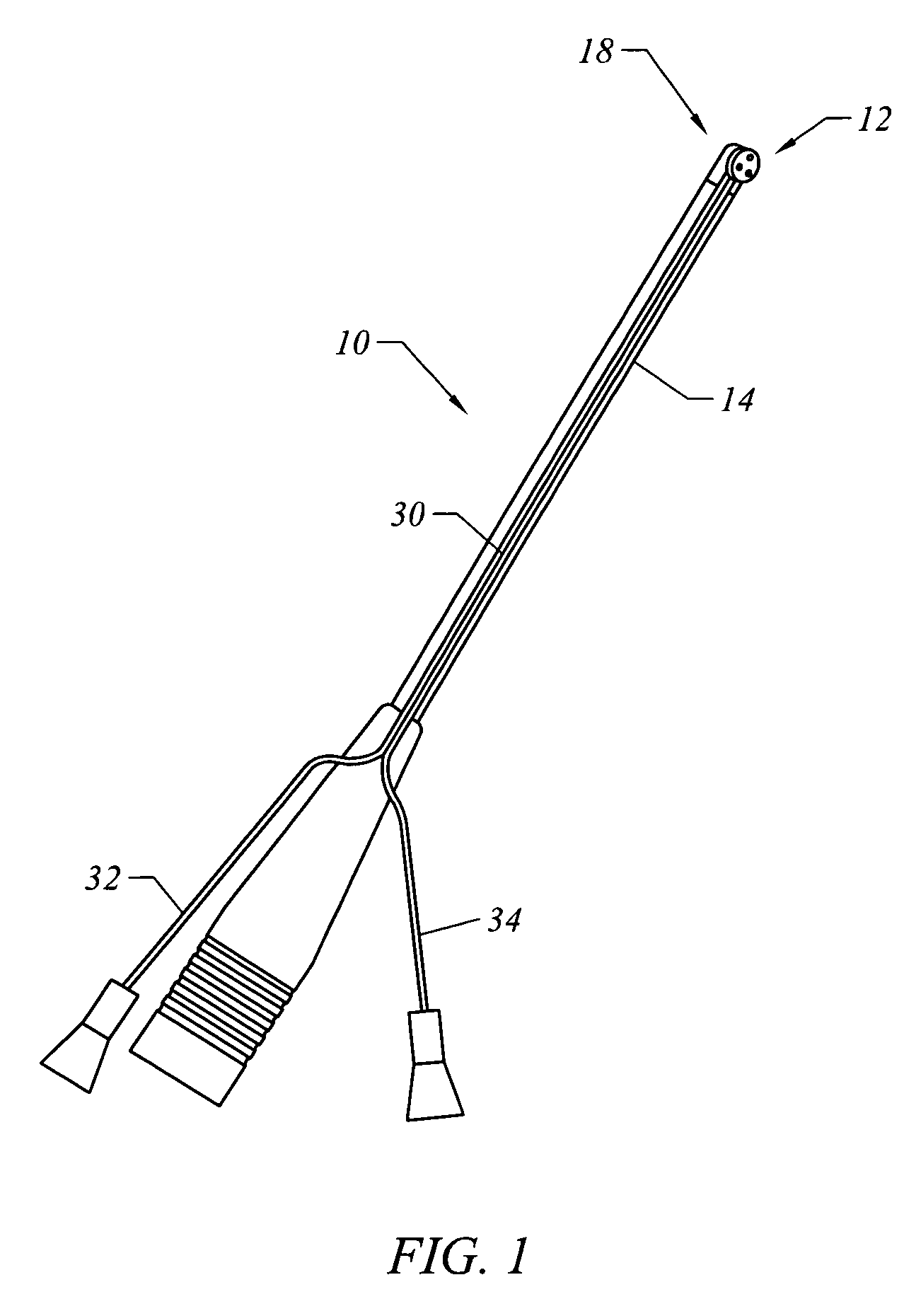
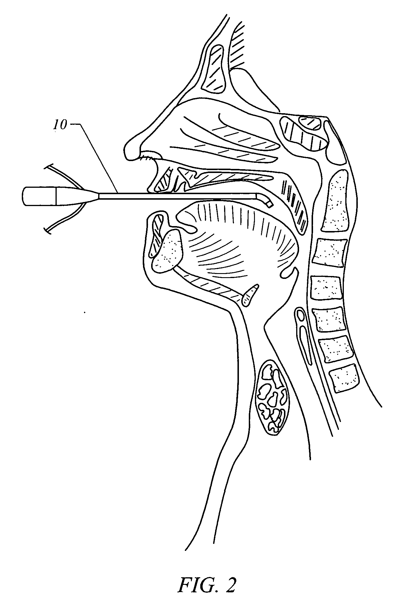
[0020] With reference to FIGS. 1-6, the present invention in one embodiment is an electrosurgical instrument (10) for performing a surgical procedure on a target site. The surgical procedure includes volumetric removal of soft tissue from the target site, for example volumetric removal of soft tissue in the throat as illustrated schematically in FIG. 2, or soft tissues at other target sites including the skin, knee, nose, spine, neck, hip, and heart.

[0021] In one embodiment as shown schematically in FIGS. 3 and 4, the instrument comprises an active electrode assembly (12) located at the distal end (18) of a shaft (14) and includes a fuse leg (16a) sized to preferentially erode and break before a break occurs on any of the anchor legs (16b and 16c) upon expiration of a predetermined amount of use of the instrument.

[0022] In another embodiment, the invention is a method of performing an electrosurgical procedure using the instrument such that the procedure is automatically stopped a...


PUM


Abstract

An electrosurgical apparatus for performing a surgical procedure on a target site, comprising a shaft having a distal end portion, the distal end portion comprising an active electrode including a fuse leg, the fuse leg adapted to break and disable the instrument upon applying a voltage differential between the active electrode and a return electrode for a predetermined amount of time. In another embodiment, the present invention is a method of performing an electrosurgical procedure on a target tissue, comprising: placing an electrosurgical instrument in close proximity to the target tissue, the electrosurgical instrument comprising an active electrode having a pre-selected portion adapted to break and disable the instrument upon applying a voltage differential thereto for a working time; and applying the voltage differential.

Description

BACKGROUND [0001] 1. Field of the Invention [0002] This invention relates to an electrosurgical apparatus, in particular an electrosurgical apparatus comprising an electrode assembly including an electrode leg adapted to break and disable the apparatus upon expiration of a predetermined amount of use of the apparatus. [0003] 2. Description of the Prior Art [0004] In electrosurgical instruments, as illustrated for example in FIG. 1, a pair of electrodes maintained at differential voltages and with dissimilar charge densities are used to conduct current to a target site to treat tissue. Treatment may include ablating, heating, cutting, removing, puncturing, probing, and otherwise stimulating tissue at the target site. The target site may include any part of a patient's body including the skin, knee, nose, spine, neck, hip, heart and the throat. See for example, U.S. Pat. No. 6,149,620 and U.S. patent application Ser. No. 09 / 457,201 herein fully incorporate by reference for description...

Claims


Application Information

Patent Timeline
Patent Type & Authority Applications(United States)
IPC IPC(8): A61B18/14
CPCA61B18/14A61B2018/1495A61B2018/00761A61B2018/00666
Inventor DAHLA, ROBERT
Owner ARTHROCARE
Why Eureka
Try Eureka