
Treadmill deck mechanism

a technology of treadmills and decks, applied in the field of treadmills, can solve the problems of increased deck stiffness, increased impact load on the user's feet, ankles and knees, and unnecessary damage to joints, and achieve the effects of increasing deck stiffness, increasing deck stiffness, and effective increasing deck stiffness

Active Publication Date: 2007-01-18
LIFE FITNESS LLC
View PDF21 Cites 28 Cited by
  • Summary
  • Abstract
  • Description
  • Claims
  • Application Information

AI Technical Summary

Benefits of technology

[0006] Accordingly, it is an object of the invention to provides a user variable deck support structure for an exercise treadmill that can be readily installed in a treadmill and that is inexpensive and easy to operate. The variable deck support structure can include the same type of resilient support members already installed in the treadmill and can use support members movable along and beneath the treadmill deck by a simple lever mechanism to provide added support for the deck thus increasing its stiffness.
[0008] A further object of the invention is to provide an exercise treadmill that includes a resilient support member attached to the deck in combination with a support member that can moved by a user such that in a first position it does not provide support for the deck and in a second position the support member is located between the deck and the treadmill frame so as to provide added support for the deck thus effectively increasing the stiffness of the deck. Additional resilient members can be attached to the deck such that the support member can be moved under more than one resilient member so as to further increase deck stiffness. Also, a user operated adjustment mechanism having a lever pivotally attached to the treadmill frame and to the support member can be used to move the support member along a longitudinal treadmill frame member to position it under selected ones of the resilient support members.
[0009] Yet another object of the invention is to provide an exercise treadmill with one or more resilient support members attached along each side of the deck with a corresponding pair of support members which are longitudinally moveable beneath the deck where the support members have a shape that is effective to support the resilient support members on the treadmill frame thereby acting to increase the stiffness of the deck when the support members are moved beneath the resilient support members. An adjustment or translation mechanism can be used to move both support members simultaneously.

Problems solved by technology

In most cases, decks are relatively rigid which can result in high impact loads on the user's feet, ankles and knees as the user's feet contact the belt and the deck.
Users often perceive this as being uncomfortable and further can result in unnecessary damage to joints as compared to running on a softer surface.
While generally successful at reducing impact loads, these approaches have certain disadvantages.
However, these approaches suffer from a number of disadvantages.
In the example described in U.S. Pat. No. 4,350,336, the location of two resilient support members can be changed but this results in uneven flexing of the deck along its length.
Moreover, these approaches do not provide a method for easy or inexpensive modification of an existing treadmill design to allow the user to vary deck flexibility or support.

Method used


Image

  • Treadmill deck mechanism
  • Treadmill deck mechanism
  • Treadmill deck mechanism

Examples


embodiment 96

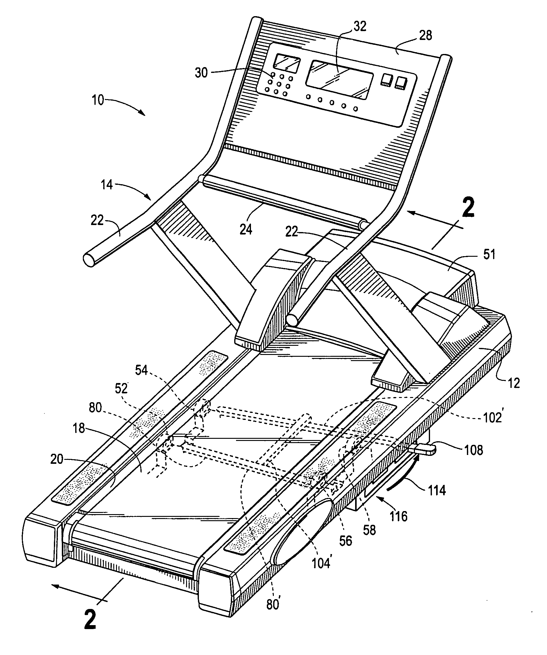
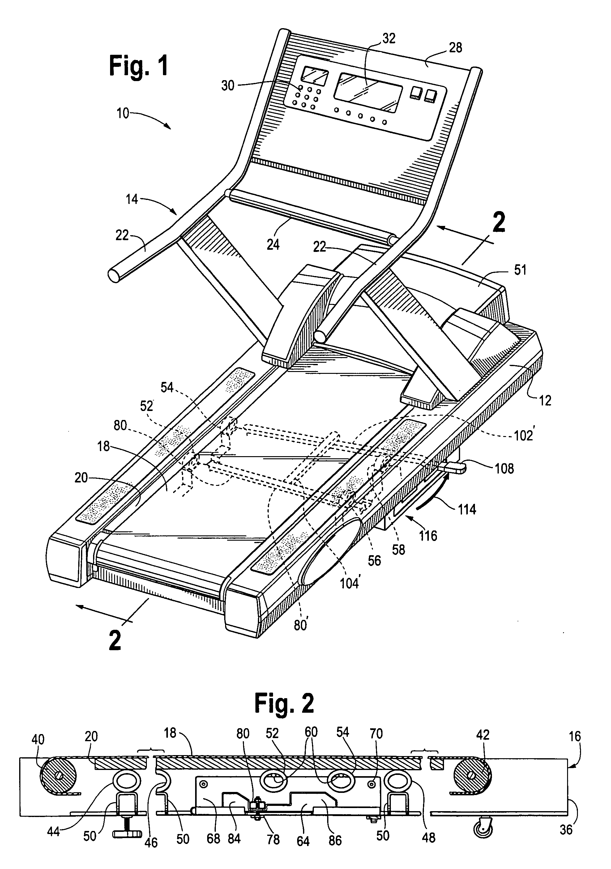
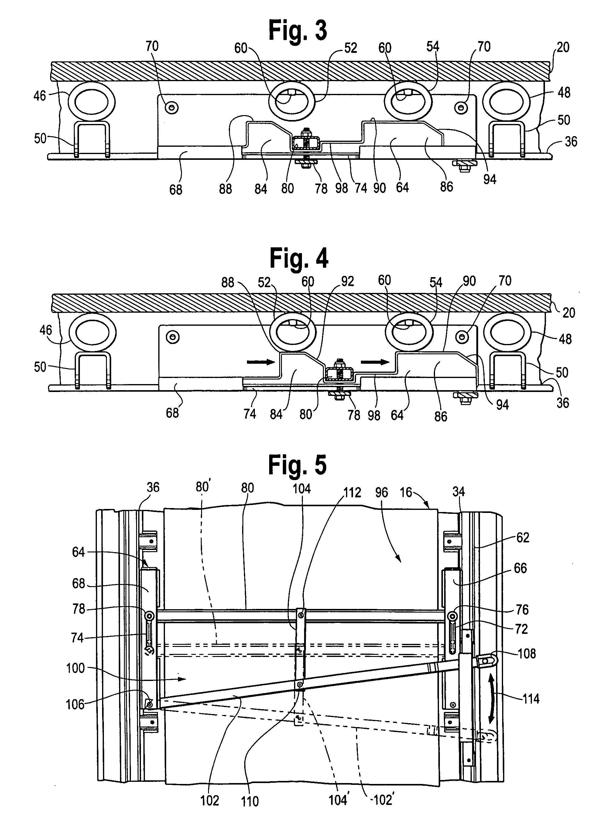
[0021] An adjustment mechanism can be used to selectively provide additional support of the deck 20 on the frame structure 16 of the treadmill 10. By increasing the support of the deck 20, by in effect adding more support members such as the resilient members 52-58, the stiffness of the deck 20 can be increased thus decreasing the downward flex of the deck 20 under the foot impact of a user. FIGS. 1-7 depict a preferred embodiment 96 of such an adjustment mechanism. Included in the adjustment mechanism 96 are the movable support members 62 and 64.

[0022] Referring first to FIG. 2, the moveable support member 64 is shown as positioned in the track 68 in a first position toward the rear of the treadmill 10. As can be seen in FIG. 2, neither of the resilient support members 52 or 54 will be engaged with the moveable support member 68 and as a result the deck 20 will tend to flex downwardly to a maximum extent.

[0023] Next referring to FIG. 3, the moveable support member 64 is shown as p...

embodiment 116

[0026] As illustrated in FIGS. 1, 6 and 7, the preferred embodiment of the invention includes a latching or retention mechanism, generally indicated at 116 that can be used to retain the moveable support members 62 and 64 in the three positions described above. In the embodiment 116 of latch mechanism shown in the figures, a bracket 118 is secured to the underside of the longitudinal frame member 34 and is configured with a set of three notches 120, 122 and 124 that effectively act as detents for the adjustment lever 102. Here, the notches 120-124 correspond to the three positions of the moveable support members 62 and 64 as described above. Included in the latch mechanism 116 is a latch member 126 that is configured to fit within each of the notches 120-124 and is secured by a fastener 128 to the end of the adjustment lever 102 and to the handle 108. In addition the fastener 128 is used to secure an elastomeric bumper 130, which abuts the underside of the bracket 118, to the latch ...


PUM


Abstract

To provide variable resilient support for the deck of an exercise treadmill one or more resilient members are secured to the deck and a moveable support member is used to selectively engage the resilient members to provide support for the deck. A user operated adjustment mechanism can be used to move the support member or support members longitudinally along the treadmill thus effectively changing the number of resilient support members supporting the deck.

Description

FIELD OF THE INVENTION [0001] The invention generally relates to exercise equipment, and more particularly to human operated exercise treadmills. BACKGROUND OF THE INVENTION [0002] Exercise treadmills are widely used for various purposes. Exercise treadmills are, for example, used for performing walking or running aerobic-type exercise while the user remains in a relatively stationary position, further, exercise treadmills are used for diagnostic and therapeutic purposes. For all of these purposes, the person on the exercise treadmill normally performs an exercise routine at a relatively steady and continuous level of physical activity. Examples of such treadmills are illustrated in U.S. Pat. Nos. 4,635,928, 4,659,074, 4,664,371, 4,334,676, 4,635,927, 4,643,418, 4,749,181, 4,614,337, 6,095,951 and 6,572,512. [0003] Exercise treadmills typically have an endless running surface which is extended between and movable around two substantially parallel pulleys at each end of the treadmill...

Claims


Application Information

Patent Timeline
IPC IPC(8): A63B22/02
CPCA63B2022/0228A63B22/02A63B22/0228
Inventor DONNER, MATTHEW A.HAUGEN, PETER H.GROSSMANN, BRADLEY H.
Owner LIFE FITNESS LLC
Learn More