Lock device

Inactive Publication Date: 2007-01-25
ASSA
View PDF21 Cites 46 Cited by
  • Summary
  • Abstract
  • Description
  • Claims
  • Application Information

AI Technical Summary

Benefits of technology

[0005] An object of the present invention is to provide a lock device of the kind initially mentioned which has a simple design and readily adapts itself for different configurations of the tailpiece.
[0009] Thus there is provided a lock device having a simple design and which still is easy to adapt to different configurations.

Problems solved by technology

The disclosed solution is however limited to lock devices of the so-called DIN standard and discloses no tailpiece at the end of a lock cylinder.

Method used


Image

  • Lock device
  • Lock device
  • Lock device

Examples


Embodiment Construction

[0015] In the following a detailed description of preferred embodiments of the present invention will be given.

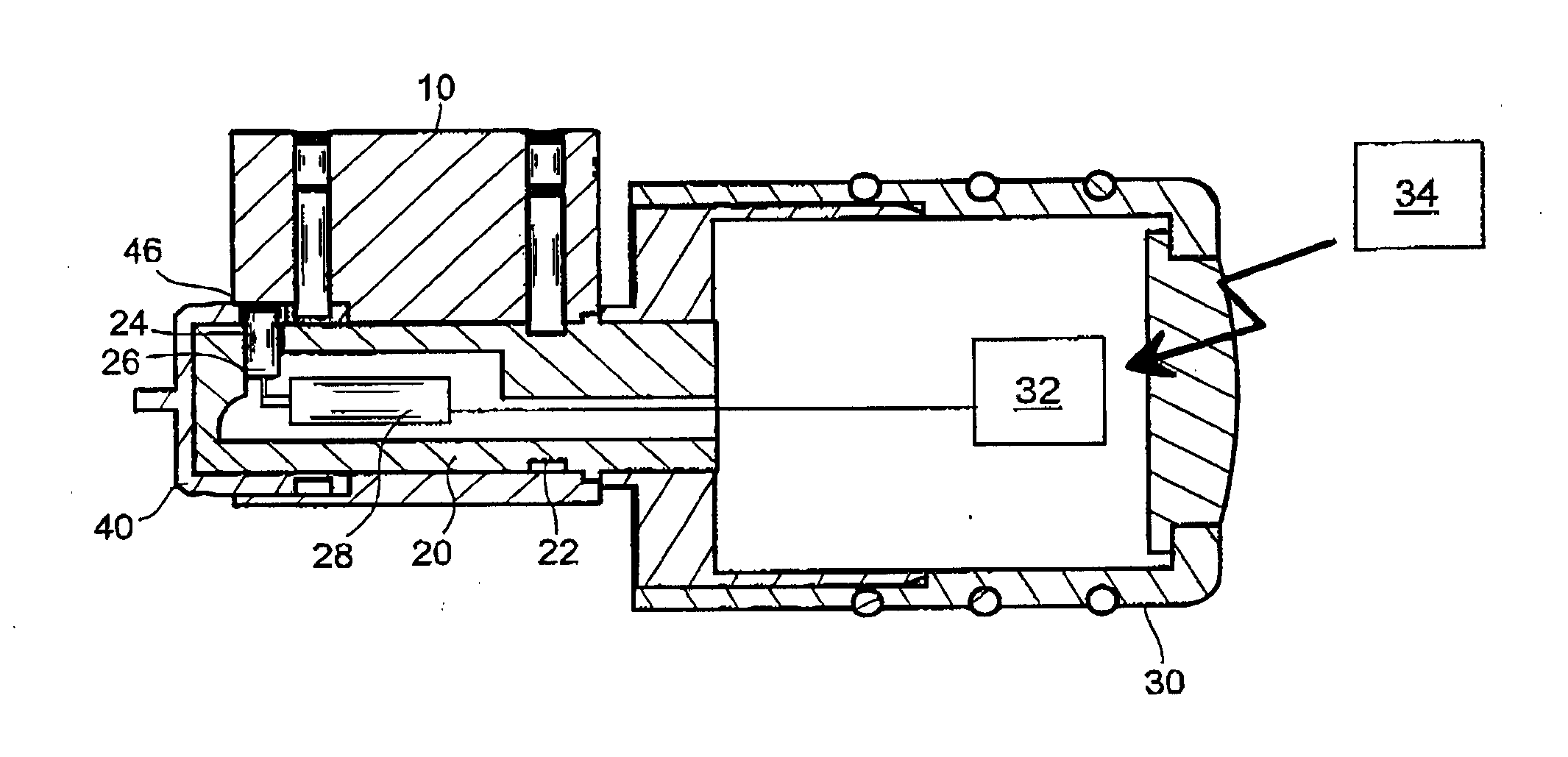
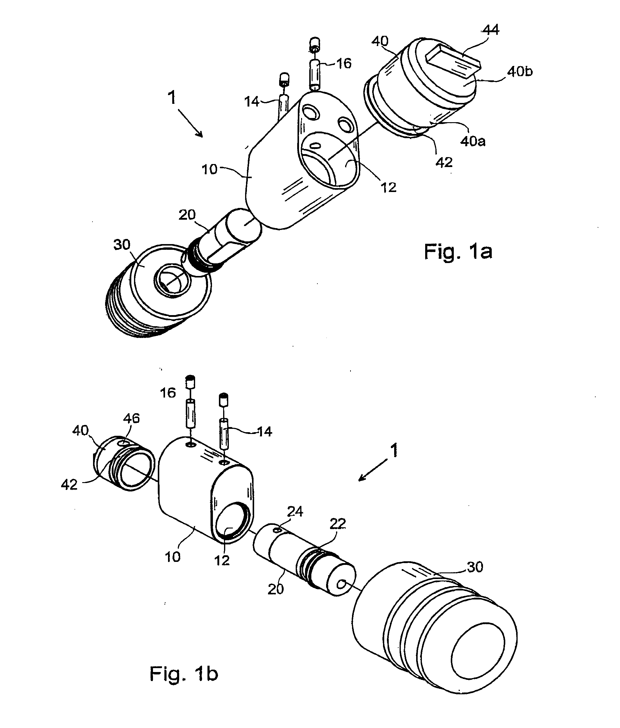
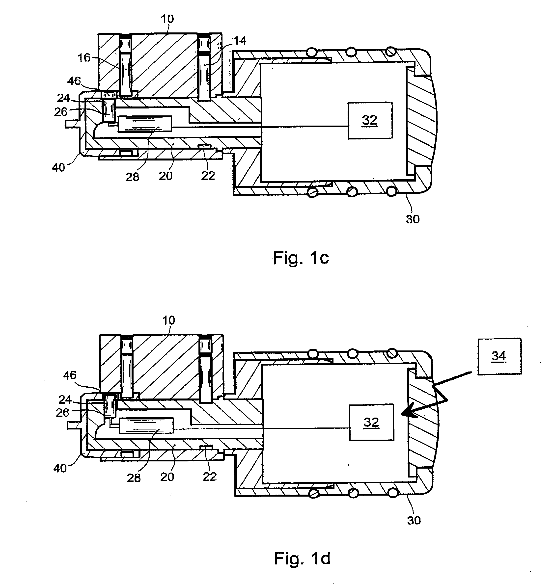
[0016] A lock cylinder, generally designated 1, is shown in exploded perspective view in FIGS. 1a and 1b. The lock cylinder comprises a cylinder house 10 having a circular cavity or bore 12 extending axially through the full length of the lock cylinder. A cylindrical cylinder core 20 is arranged rotatably in the cavity and is fixated axially by means of a lock pin 14 in the cylinder house engaging a circumferential groove 22 on the envelope surface of the cylinder core. A knob 30 is attached to the outer end portion of the cylinder core 20. This knob comprises electronic authorization means, such as a microprocessor, control electronics, antenna etc., generally designated 32, see FIGS. 1c and 1d.

[0017] A cup shaped tailpiece 40 having a cylindrical portion 40a and an essentially planar bottom 40b is rotatably provided in the cavity 12 at the end opposite to the end at whi...


PUM


Abstract

A lock device comprises a cylinder house (10) and a substantially cylindrical cylinder core (20), which is rotatably accommodated in the cylinder house and fixed against axial displacement relative thereto. A tailpiece (40) is rotatably accommodated in the cylinder house and fixed against axial displacement relative thereto. An interconnection means, such as a pin (26), is radially moveable between a disconnecting position, wherein it engages only the cylinder core, and an interconnecting position, wherein it engages both the cylinder core and the tailpiece. By providing an interconnection means that is movable radially to engage a tailpiece, a simple and yet flexible design is achieved.

Description

FIELD OF INVENTION [0001] The present invention relates generally to lock devices and more particularly to a lock cylinder having a free-turning function between the cylinder core and the tailpiece. BACKGROUND [0002] Lock cylinders are arranged to transfer a rotational movement from a cylinder core to a tailpiece provided to actuate a lock mechanism in for example a lock case the cylinder core can be turned by means of e.g. a key or a knob. In many lock cylinders, a blocking mechanism is provided to allow only an authorized user to operate the lock cylinder. This blocking mechanism prevents turning of the cylinder core for example in the case an incorrect key is inserted in the lock cylinder. [0003] As an alternative to a blocking mechanism preventing turning of the cylinder core, an arrangement can be provided which decouples or disconnects the cylinder core from the tailpiece. In this case, when an incorrect key is inserted in the lock cylinder, the cylinder core can be freely rot...

Claims


Application Information

Patent Timeline
IPC IPC(8): E05B17/04E05B9/10
CPCE05B47/0012E05B47/0615E05B2047/0094E05B47/0692E05B2047/0016E05B47/0649Y10T70/7706
Inventor ANDERSSON, DANIEL
Owner ASSA
Why Eureka
Try Eureka