
Susceptors capable of balancing stress and effectiveness

Inactive Publication Date: 2007-02-01
GRAPHIC PACKAGING INT
View PDF39 Cites 22 Cited by
  • Summary
  • Abstract
  • Description
  • Claims
  • Application Information

AI Technical Summary

Benefits of technology

[0015] In accordance with an aspect of the present invention, the layer(s) of microwave interactive material are configured in a manner that seeks to restrict heating of the periphery of the turntable tray by the microwave interactive material.
[0017] In accordance with one embodiment of the present invention, the periphery of the layer of microwave interactive material is absent of acute corners (e.g., absent of a corner formed by edges that meet at an angle of 90 degrees or less). In contrast, the corners of the layer of microwave interactive material can be beveled (e.g. rounded, truncated, or the like) so that they seek to limit the peak thermally induced stress in the turntable tray.
[0018] The at least one layer of microwave interactive material can include first and second layers of microwave interactive material. For example, the first layer can be substantially continuous, whereas the second layer can be discontinuous (e.g., patterned), with the second layer being adjacent and extending outwardly from the periphery of at least a portion of the first layer. Per unit area, the second layer absorbs less microwave energy, and thereby becomes less hot, as compared to the first layer. This arrangement seeks to limit the peak thermally induced stress in the turntable tray.
[0021] More specifically, an example of an aspect of the present invention is the configuring of the periphery of one or more layers of microwave interactive material, which is for becoming hot when exposed to microwave energy, in a manner that seeks to advantageously control heating, so that the periphery of the microwave interactive material can typically safely be adjacent the periphery of a turntable tray.

Problems solved by technology

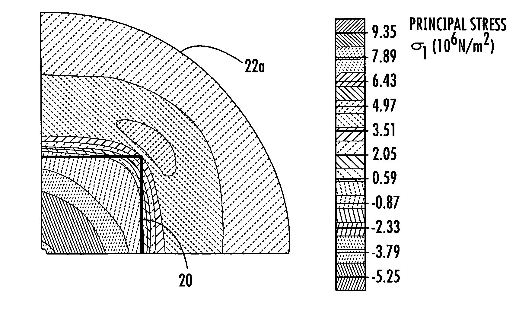
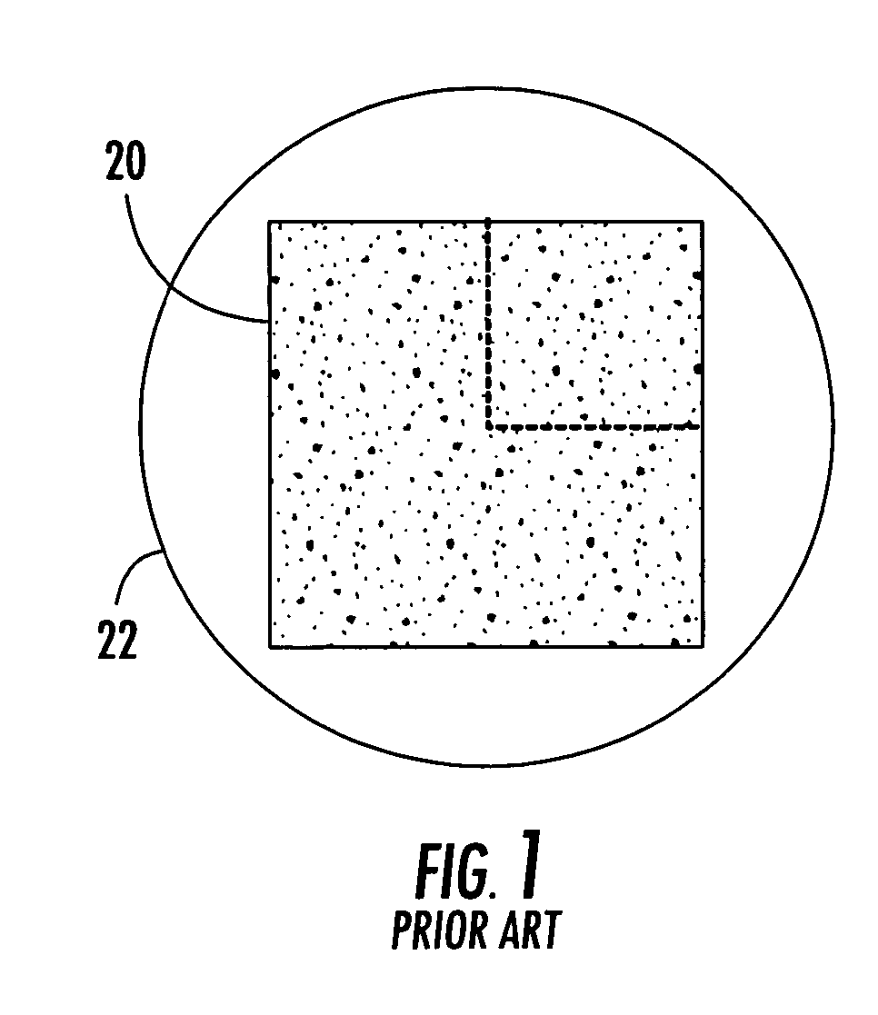
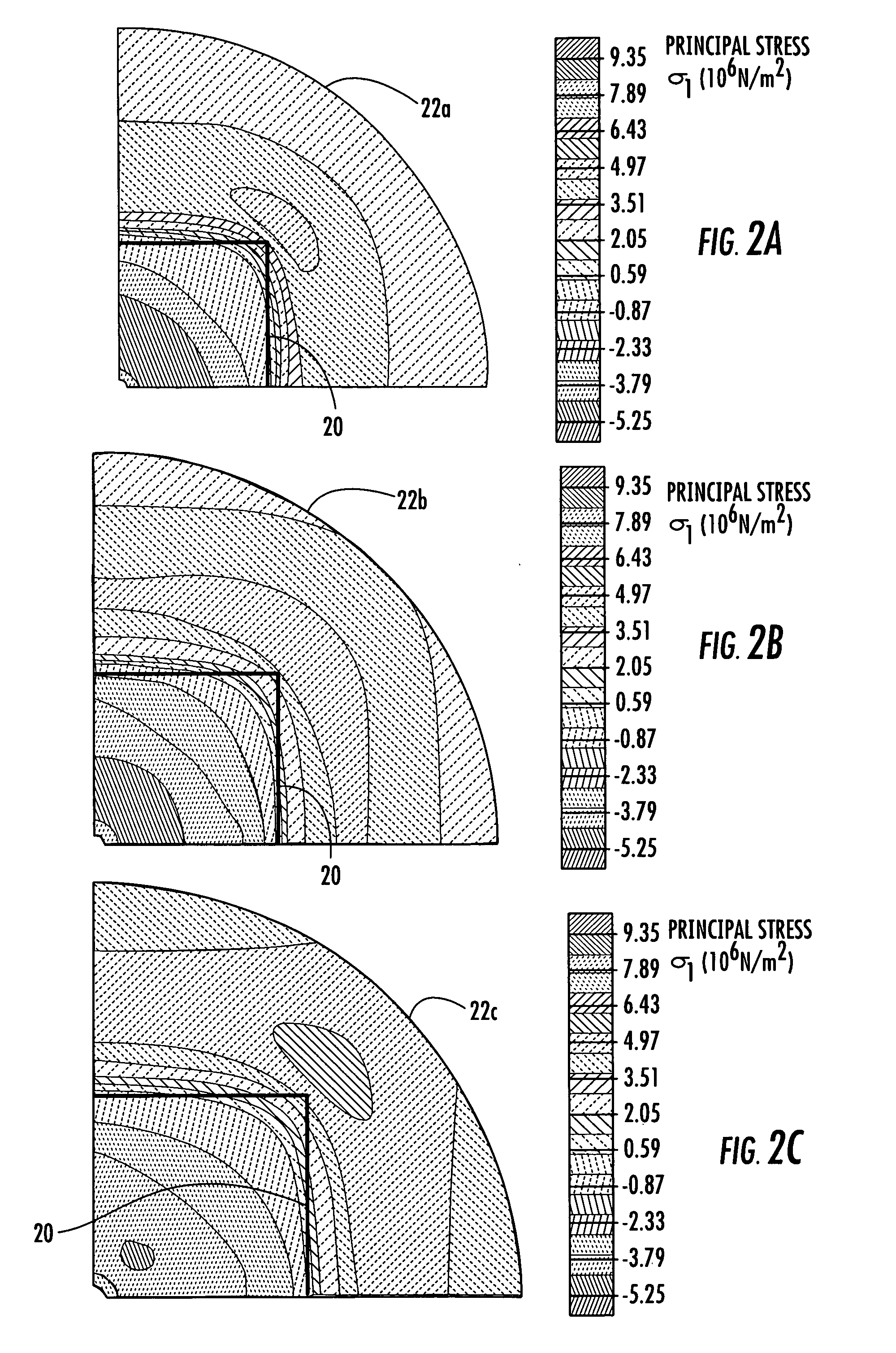
In particular, corners of the susceptor may be proximate the periphery of the turntable tray, and heat transferred from those corners of the susceptor to the turntable tray can lead to damaging thermally induced stress in the turntable tray, namely proximate the periphery of the turntable tray.
Even a relatively small susceptor that is sufficiently off-center on a relatively large turntable tray can cause the peak thermally induced stress to be disadvantageously located at, or proximate, the perimeter of the turntable tray.
It can be disadvantageous to have peak thermally induced stress that is located at, or proximate, the perimeters of turntable trays.
For example, fractures and cracks tend to initiate at the edges of turntable trays because stress-enhancing defects, such as chips, are common at the edges of turntable trays.
Bringing stress-enhancing defects and the peak thermally induced stresses together increases the possibility of fracturing turntable trays made of glass, and the like.

Method used


Image

  • Susceptors capable of balancing stress and effectiveness
  • Susceptors capable of balancing stress and effectiveness
  • Susceptors capable of balancing stress and effectiveness

Examples


first embodiment

[0045]FIG. 3A is a schematic top plan view of a construct or package's bottom panel 120 that can be placed upon a disk-shaped tray of a turntable (e.g., see turntable tray 22 of FIG. 1) in a microwave oven (not shown), in accordance with a first embodiment of the present invention. The bottom panel 120 is shown in isolation in FIG. 3A. As best understood with reference to FIG. 3B, in some versions of the first embodiment, the package that includes the bottom panel 120 is an open-top tray so that four side panels 121a-d, or the like, extend upwardly respectively from the four edges of the bottom panel 120. In some versions of the first embodiment, the package is a box, so that not only are there four side panels 121a-d that extend upwardly respectively from the four edges of the bottom panel 120, but there is also a top panel or lid 122, or the like, for closing the tray-like portion of the package. As shown in FIG. 3B, the lid 122 is pivotably connected by a fold line to the upper e...

second embodiment

[0080]FIG. 4 illustrates a bottom panel 220 of a second embodiment of the present invention. The first and second embodiments are alike, except for variations noted and variations that will be apparent to those of ordinary skill in the art.

[0081] In addition to the central region 224 of the upper surface of the lower support layer (e.g., see the lower support layer 130 shown in FIG. 3C) of the bottom panel 220 being entirely covered with a continuous layer of microwave interactive material (e.g., see the continuous layer of microwave interactive material 125 of FIG. 3C), the corner regions 230 of the upper surface of the lower support layer of the bottom panel 220 are entirely covered with a patterned layer of microwave interactive material. The continuous layer of microwave interactive material is schematically represented by the relatively heavy stippling in FIG. 4. The patterned layer of microwave interactive material is schematically represented by the relatively light stipplin...

third embodiment

[0086]FIG. 5 illustrates a bottom panel 320 of a third embodiment of the present invention. The second and third embodiments are alike, except for variations noted and variations that will be apparent to those of ordinary skill in the art.

[0087] The upper surface of the lower support layer (e.g., see the lower support layer 130 shown in FIG. 3C) of the bottom panel 320 includes a circular central region 324 that is entirely covered with a continuous layer of microwave interactive material (e.g., see the continuous layer of microwave interactive material 125 shown in FIG. 3C). The continuous layer of microwave interactive material is schematically represented by the relatively heavy stippling in FIG. 5. The central region 324 is surrounded by a marginal region 332 that extends between the periphery of the central region 324 and the edges of the bottom panel 320. More specifically, the marginal region 332 extends between the periphery of the continuous layer of microwave interactive ...


PUM


Abstract

An outer portion of one or more layers of microwave interactive material, which is for becoming hot when exposed to microwave energy, is arranged in a manner that seeks to advantageously control heating, so that the outer portion of the microwave interactive material can safely be adjacent the periphery of a turntable tray. The turntable tray can be heated by the microwave interactive material so that a peak thermally induced stress occurs in the turntable tray at a position proximate the periphery of the tray. The layer(s) of microwave interactive material are configured in a manner so that the peak thermally induced stress is less than a predetermined amount.

Description

CROSS-REFERENCE TO RELATED APPLICATION [0001] The present application claims the benefit of U.S. Provisional Application No. 60 / 691,885, which was filed Jun. 17, 2005. The entire disclosure of U.S. Provisional Application No. 60 / 691,885, which was filed Jun. 17, 2005, is incorporated herein by reference.BACKGROUND OF THE INVENTION [0002] The present invention generally relates to microwave energy interactive materials (“microwave interactive materials”) and, more specifically, to the shape of susceptors. [0003] Microwave ovens are frequently used to heat food. As a result, the number of food items and constructs (e.g., packages) available for use with a microwave oven is increasing. It is well known for such a construct to include a layer of microwave energy interactive material (“microwave interactive material”) that is for interacting with microwave energy in a manner that reduces, enhances or otherwise alters the effectiveness of a microwave oven. There are several types of micro...

Claims


Application Information

Patent Timeline
IPC IPC(8): H05B6/80A23L5/10A23L19/12
CPCB65D81/3446B65D2581/344B65D2581/3452B65D2581/3454B65D2581/3472H05B6/6494B65D2581/3498A23L1/0128A23V2002/00H05B6/6411B65D2581/3494A23L5/15
Inventor RUSSELL, ANTHONYCOLE, LORIN R.MIDDLETON, SCOTT W.
Owner GRAPHIC PACKAGING INT
Learn More