Method of processing ceramic materials and a microwave furnace therefore

a microwave furnace and ceramic material technology, applied in the field of ceramic material processing and microwave furnace, can solve the problems of large thermal mismatch between the centre and the surface, mass transfer, temperature gradient across the specimen,

Inactive Publication Date: 2001-01-09
CAPENHURST TECH
View PDF19 Cites 62 Cited by
  • Summary
  • Abstract
  • Description
  • Claims
  • Application Information

AI Technical Summary

Benefits of technology

According to the first aspect of the present invention there is provided a method of processing ceramic materials comprising the steps of providing a microwave furnace of the type comprising a microwave source, an enclosure for the confinement of microwave energy and for containing an object to be heated, means for coupling the microwave source to said enclosure, and independently controllable alternate heating means comprising at least one of radiant and convective heating means, said alternate heating means being disposed in relation to said enclosure to provide radiant and / or convective heat within the enclosure, energizing said alternate heating means independently of the microwave energy in the enclosure so as to generate said at least one of the radiant and convective heat substantially throughout the heating cycle of the furnace and at temperatures up to and including sintering temperatures, and controlling the quantity of heat generated in the object by both of the microwave energy and said at least one of radiant and convective heat so as to provide a desired thermal profile in the object.
When the glass is present the microwaves will be preferentially absorbed by them setting up a transient differential heating pattern, with the polycrystalline grains normally absorbing less microwave energy and so being at a lower temperature. Heat will therefore flow from the glass to the grains establishing uniformity of temperature. In a steady state situation, for example when at a holding temperature, equilibrium will be established quickly and the temperature gradients at any one point within the material will be a minimum. However, during the heating or cooling of the material the glass may be at a significantly higher temperature. This would account for the increased sintering rate which is observed for a given temperature when microwaves are present because under these circumstances the heat is being deposited where it is needed, ie. at the grain boundaries. Furthermore, if the microwave energy is being preferentially deposited at the grain boundaries then it will further assist the uniformity of heating above the glass eutectic point.

Problems solved by technology

In glass and glass-ceramics the main limitation is also one of mass transfer, as the infra-red radiation cannot significantly penetrate the surface of the glass, particularly if the glass is colored.
During sintering the high radiant loading required to accomplish the task in a fixed time period results in the temperature gradient across the specimen, which is determined primarily by the thermal conductivity, becoming steep with the surface at a much higher temperature than the center.
Since the thermal conductivity of a typical unsintered homogeneous material is extremely low (i.e. less than 1W / mK), there is a tendency in larger components for the temperature gradient to result in a large thermal mismatch between the centre and the surface.
During the first stages of heating, if the component is heated uniformly on all sides, the described thermal mismatch generates compressive thermal stresses at the surface, and as a result the propagation of cracks is inhibited and failures are comparatively rare.
However if the thermal gradient is sufficiently large, cracking will occur.
Unfortunately it has been found that this maximum temperature gradient varies with both the material and temperature making it difficult to predict and necessitating extensive trials to determine the optimum firing schedule for each component and material composition.
Where the radiant heating is non-uniform, for example, if the components are stacked or the subject of multiple firing, one side of the component will be in tension and prone to crack propagation.
In extreme cases catastrophic fracture can occur while in less severe cases the stresses may still cause distortion of the components.
Whether the heating is either uniform or non-uniform, once the sintering regime is reached, the linear shrinkage associated with the densification process tends to over shadow the thermal mismatch and allow some relaxation of the thermal stresses with the consequence that the stress distribution becomes more complicated to predict.
However, in order to rapidly fire a component in a short time period it is necessary to use high radiant surface loadings and this in turn provides the heating elements with a difficult role to perform and shortens their life expectancy considerably necessitating the use of higher rated and more expensive elements.
The presence of a severe temperature gradient, apart from causing cracking, can also result in uneven sintering, with the surface sintering before, and at a faster rate than the centre.
This can result in non-uniform properties within the material, which can make a predetermined quality specification difficult to meet and can lead to the generation of a lot of waste material, particularly if the final component is to be machined from a larger block.
This requires specific firing schedules which for the above reasons are clearly difficult to attain and so restricts the design of the components.
This makes the firing process not only energy intensive, which naturally tends to favor non-electrical methods of heating, but also highly capital and labor intensive.
These factors all contribute to slow the uptake of new processes and products which involve the sintering of ceramics since at the same time these processes and products significantly lower the net value to the company of the project concerned.
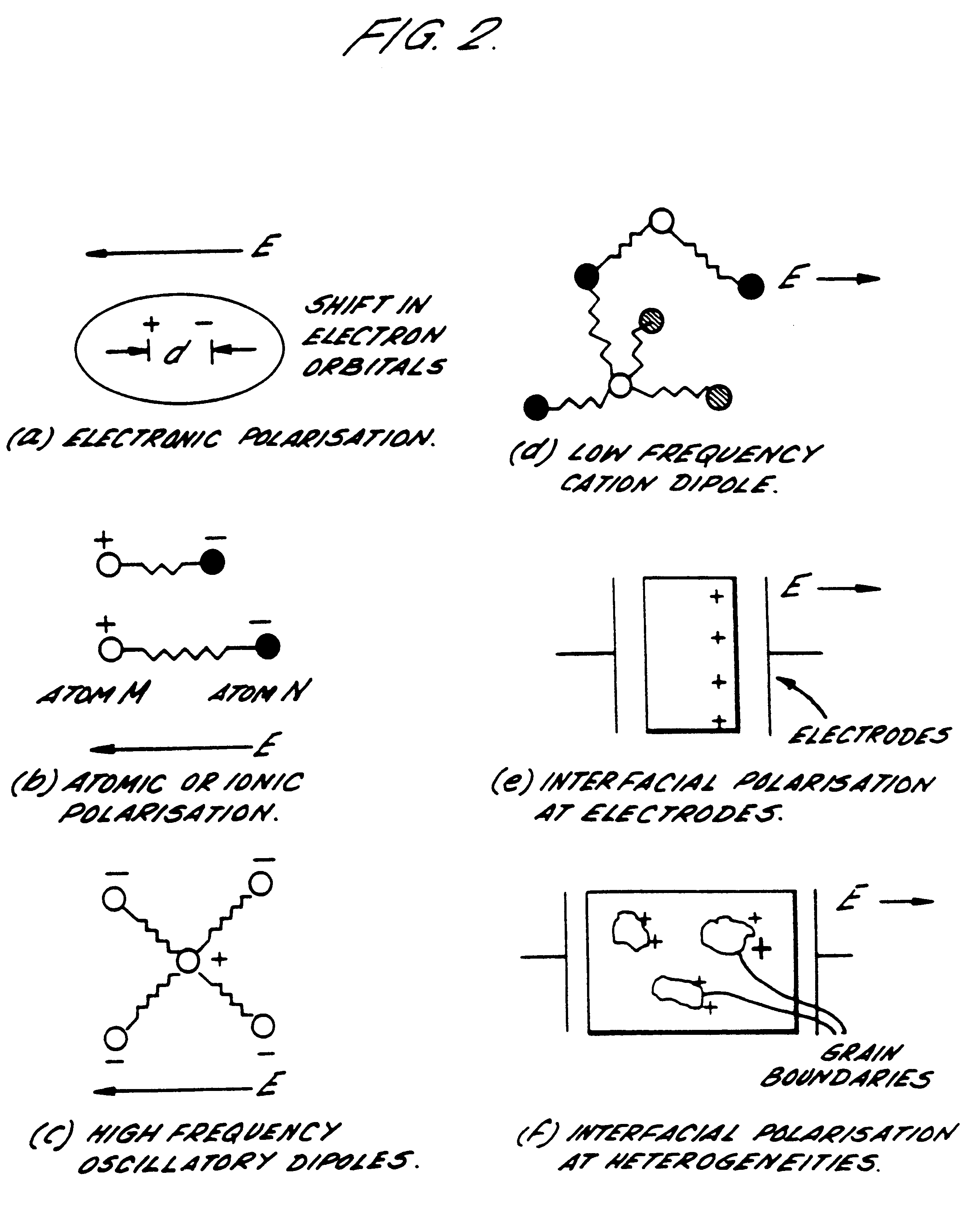
However ceramics, being principally non-conductive, require the use of the much higher frequencies of the microwave band before effective coupling can be achieved.
However, despite these claims, recent developments have highlighted a number of potentially serious drawbacks to microwave-only firing which have been identified as the cause of numerous failed attempts to fire realistically sized components.
This in turn has led to significant scepticism within the ceramic industry as to the value of microwave firing.
In practice, however, difficulties arise when heating a body to high temperature using only microwave energy and these often result in thermal stress fractures.
As the temperature of the body increases, the heat losses become greater, and the magnitude of this temperature difference increases.
Although it is possible to generate extremely high field intensities within carefully tuned resonant chambers, the multi-mode cavity more realistically used for large scale processing is usually limited to a Q factor of less than 200.
Many ceramics, such as alumina, exhibit relatively small losses, i.e. they have relatively poor microwave absorption characteristics, at low to intermediate temperatures and so do not heat quickly in the field strengths of a typical multi-mode cavity.
However as they approach a critical temperature, the losses increase dramatically and an effect known as thermal break-away can occur.
Thus many such microwave-only heating arrangements can be considered as intrinsically self-destructive.
The first of these has long been recognised as a major cause of thermal break-away or the generation of hot-spots in situations where the skin depth is larger than the typical thickness of the material concerned.
The use of this frequency for commercial applications however is impractical owing to the associated high capital cost and other factors such as the more limited microwave penetration.
The third factor identified as leading to thermal break-away can be related to the fact that the absorption of microwave energy is no longer uniform once temperature differences have been established, particularly in cases where the loss factor, which controls the amount of power absorbed by the material, increases exponentially with temperature.
Under these circumstances it is simply not possible for the heat to be transferred to the surface of the component sufficiently quickly in order to prevent thermal break-away.
One problem that is closely related to thermal break-away is that not all materials are able to efficiently absorb microwave energy at ambient temperatures and must first be heated to a more elevated temperature.
The raising of the material to this more elevated temperature using microwave heating can be a time consuming and inefficient process since to start off with it is characterised by a long dwell period in which only a small rise in temperature is evident.
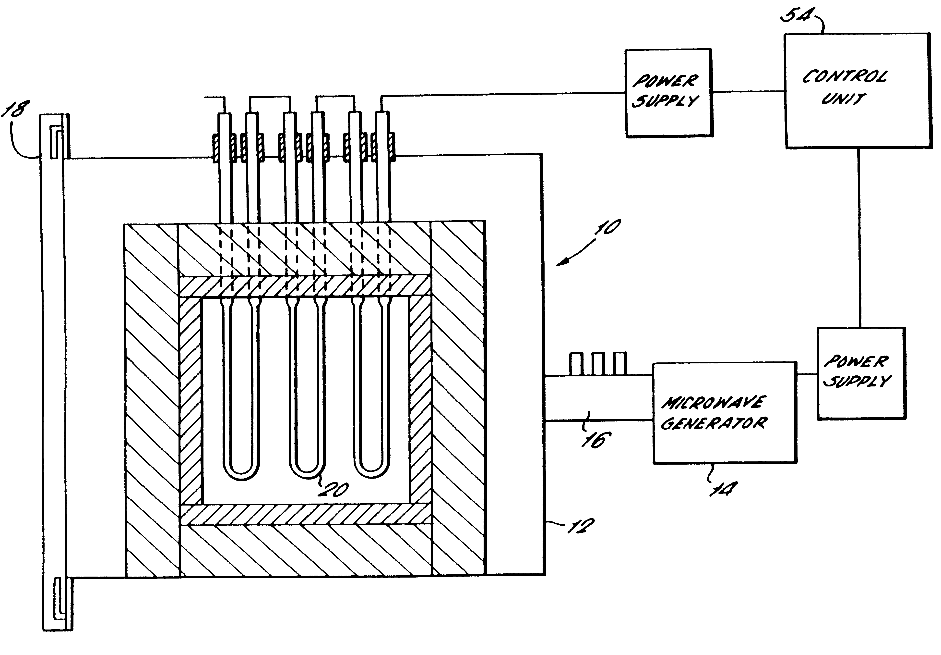
To date however, these attempts have been limited to the laboratory and have comprised the placement of a microwave cavity constructed from austenitic stainless steel within a conventional electric resistance furnace.
Due to the limitations of the cavity material however, it is doubtful whether pre-heating can be taken beyond 1000.degree. C.
Furthermore, the requirement for extensive insulation material to be placed around the components to prevent the austenitic stainless steel from overheating makes the process very cumbersome.
However, these attempts have also suffered from certain drawbacks.
In the first place, the use of susceptors does not permit full control of the proportion of heat absorbed by the susceptors, insulation materials and specimens as would be required on an industrial scale.
There are also problems in maintaining a uniform temperature distribution in a purely microwave heated system under steady state conditions.

Method used


Image

  • Method of processing ceramic materials and a microwave furnace therefore
  • Method of processing ceramic materials and a microwave furnace therefore
  • Method of processing ceramic materials and a microwave furnace therefore

Examples


Embodiment Construction

Referring now to FIG. 3, there is shown a hybrid microwave furnace 10 comprising a microwave cavity 12, a microwave generator 14 and a waveguide 16 for transporting microwaves from the microwave generator 14 to the microwave cavity 12. In a currently preferred embodiment the microwave cavity has a width of 455 mm, a depth of 435 mm and height of 390 mm. This in turn provides a sample volume of 150 mm.times.150 mm.times.200 mm which in use is closed by the shutting of a door 18 incorporating a quarterwave choke microwave seal. A mode stirrer (not shown) is incorporated within the microwave cavity 12 with a fail-safe mechanism for switching off the microwave power in the event of the mode stirrer failing.

A plurality of non-retractable, radiant kanthal resistance heating elements 20 project through a wall of the microwave cavity 12 and into the sample volume. By ensuring that the heating elements 20 are highly conductive their skin depth is kept to a minimum and with it the amount of m...


PUM

PropertyMeasurementUnit
lengthaaaaaaaaaa
lengthaaaaaaaaaa
frequenciesaaaaaaaaaa

Abstract

A microwave furnace (10) of the type comprising a microwave source (14), coupled to an enclosure for the confinement of microwaves and for containing an object to be heated (12). An independently controllable alternate heating (20) is disposed in relation to the enclosure (12) to provide at least one of radiant and convective heating within the enclosure. The method comprises the steps of energizing the alternate heater (20) so as to generate heat substantially throughout the heating cycle of the furnace (10) and controlling the quanity of heat generated in the object y one or both of the microwaves and the alternate heater so as to provide a desired thermal profile in the object. A temperature sensor to measure the ambient temperature within the enclosure (12) can be provided and control circuit (54) responsive to the sensed temperature controls the quanity of heat generated in the object by the microwaves and the alternate heat so as to provide a desired thermal profile within the object.

Description

The present invention relates to the microwave-assisted processing of ceramic materials. To that end there is described a microwave furnace and a method of operating a microwave source, an enclosure for the confinement of the microwave and for containing an object to be heated, means for coupling the microwave source to the enclosure and independently controllable alternate heating means disposed in relation to the enclosure to provide at least one of radiant and convective heating within the enclosure.The volumetric heating of ceramic materials using microwaves can in principle be used to overcome many of the difficulties associated with the inherently poor heat transfer characteristics of ceramic components and certain glasses such as dark colored glass or glass ceramics. The following will therefore primarily concentrate on ceramic materials and components, however it will be appreciated that the teaching provided is also applicable to any material which requires heating and exhi...

Claims


Application Information

Patent Timeline
Patent Type & Authority Patents(United States)
IPC IPC(8): B01J19/12H05B6/80
CPCB01J19/126B01J19/129H05B6/80B01J2219/1227H05B2206/046
Inventor WROE, FIONA CATHERINE RUTH
Owner CAPENHURST TECH
Why Eureka
Try Eureka