Semiconductor laser drive control device

a technology of laser drive and control device, which is applied in the direction of digitally marking record carriers, visual presentation using printers, instruments, etc., can solve the problems of deteriorating image quality, reducing light amount, and linearity of laser emission, so as to improve gradation characteristics

Inactive Publication Date: 2007-02-01
CANON KK
View PDF4 Cites 0 Cited by
  • Summary
  • Abstract
  • Description
  • Claims
  • Application Information

AI Technical Summary

Benefits of technology

[0019] It is therefore an object of the present invention to solve such problems and provide a semiconductor laser drive control device capable of improving gra

Problems solved by technology

Accordingly, challenges have arisen to provide excellent dot reproducibility in a highlight region and to reproduce a high-density dot and a high-density line such as an outline character and an outline line.
In order to fulfill the requirement for the higher density in a recording resolution, an increase in speed of a laser driver device is a must; however, the increase in speed causes the following negative effect.
That is, an amount of light is decreased due to a defective rising of a laser emission in a highlight region, whereas an amount of light is increased due to a defective falling of the laser emission in a high-density region, and therefore linearity of the laser emission is reduced, whereby image quality is deteriorated.
However, it has not been able to correct collapse of the resolution due to a defective falling of a laser optical signal in a high-density region where a signal of the laser optical signal changes from an intermittent mode to a continuous mode.
In the case of carrying out a correction in a specific region comprised of only a highlight region or high-density region, because an appropriate correction over all gradations has not been possible, the gradations have become discontinuous between correction application and non-applicatio

Method used


Image

  • Semiconductor laser drive control device
  • Semiconductor laser drive control device
  • Semiconductor laser drive control device

Examples


embodiment 1

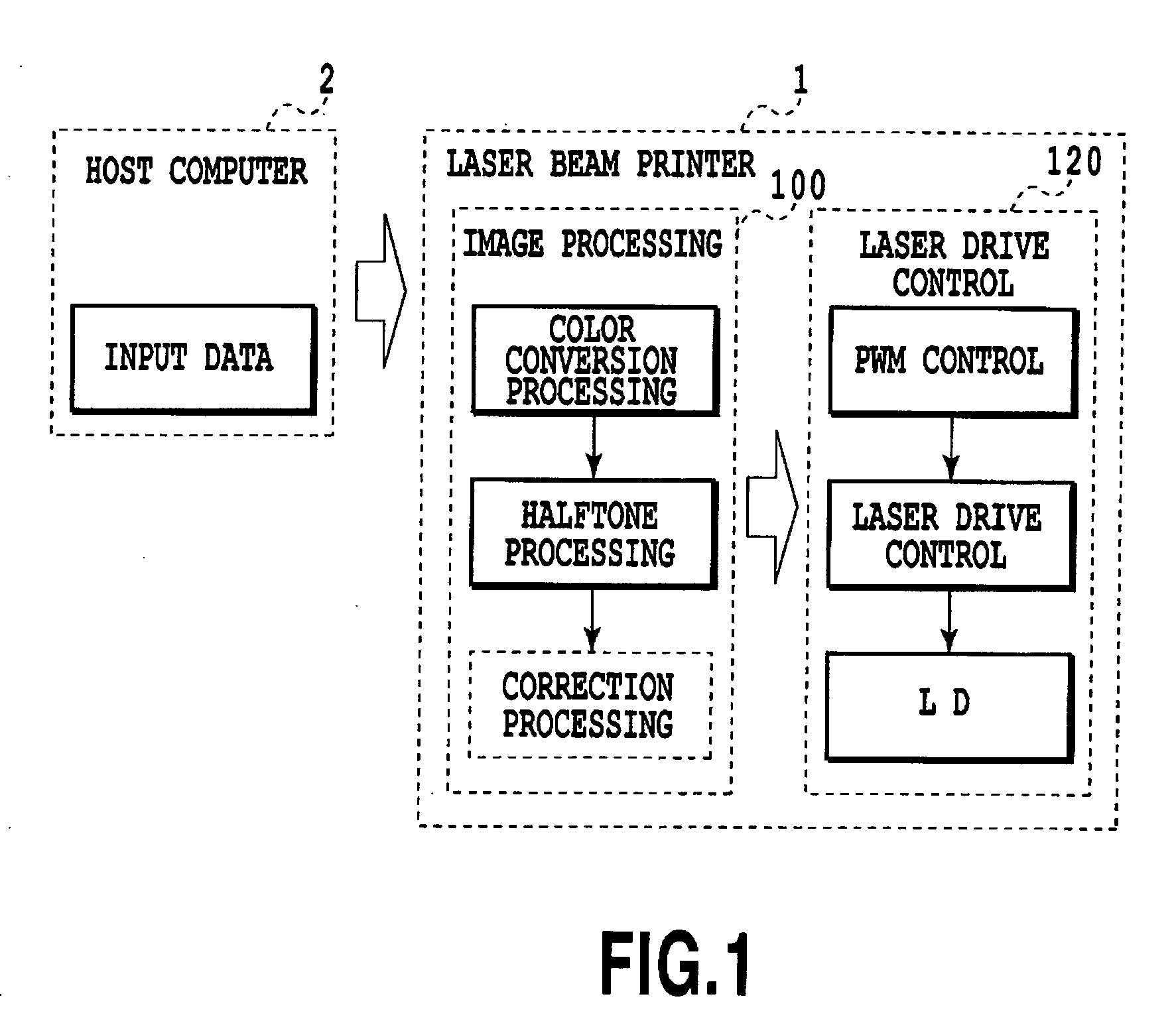
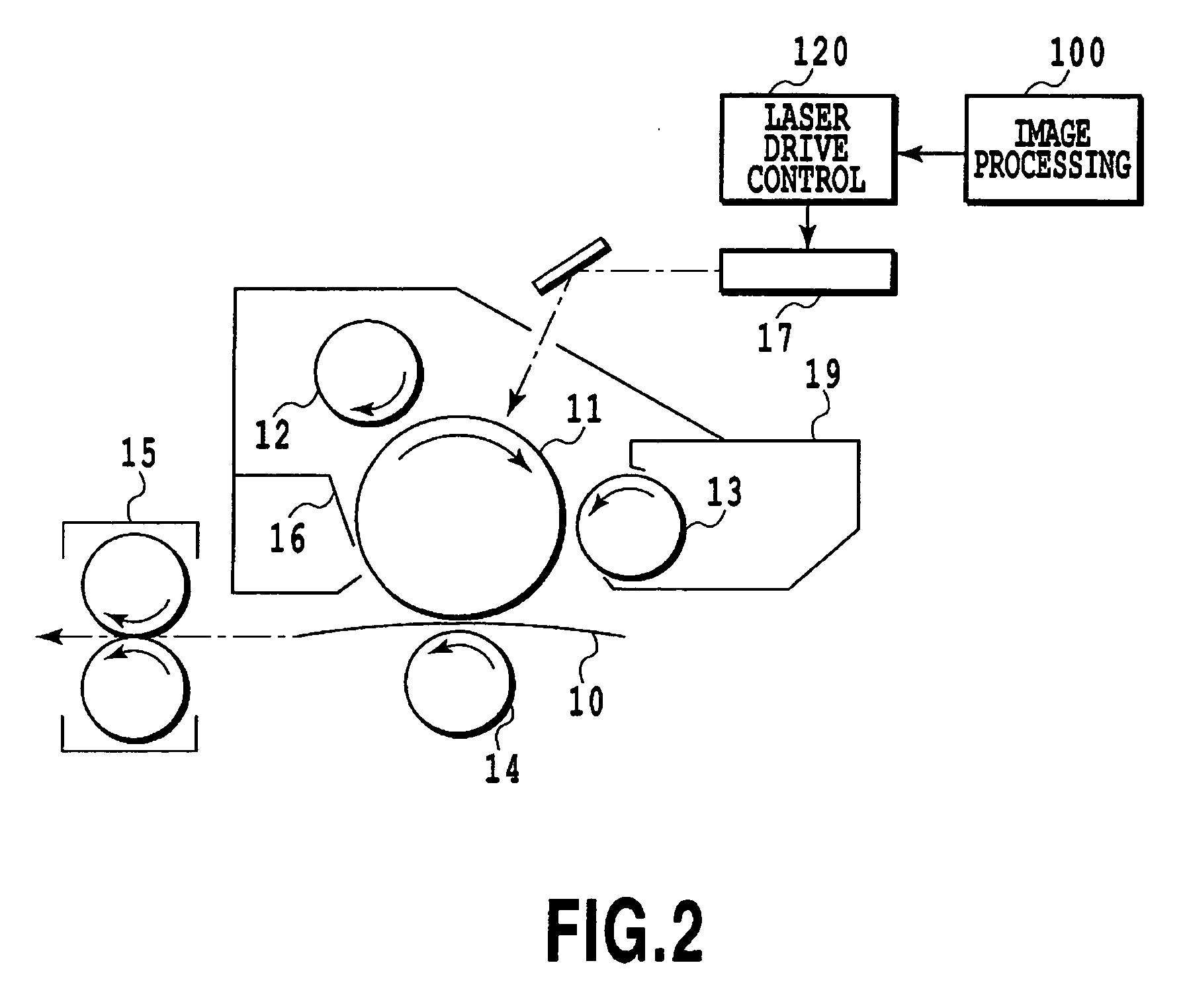
[0061]FIG. 1 illustrates a first embodiment of the present invention. This is an example of a laser beam printer which is shown in FIG. 2.

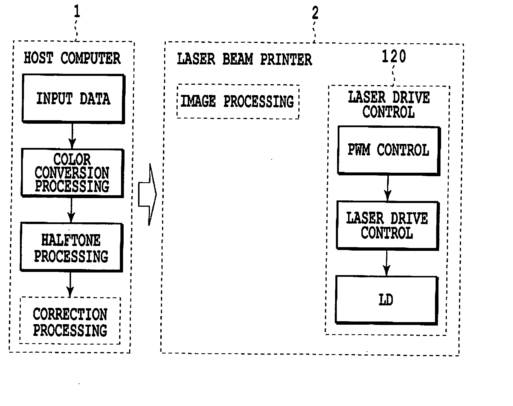
[0062] In FIG. 1, the reference numeral 1 represents the laser beam printer, which employs a pulse width modulation (PWM) system as the system for converting multivalued data into an amount of irradiating light and comprises an image processing 100 and a laser drive control 120. The image processing 100 performs color conversion processing and halftone processing based on input data from a host computer 2 connected to the laser beam printer 1, and further performs correction processing. The laser drive control 120 performs a PWM control to drive and control a semiconductor laser based on the image data processed in the image processing 100.

[0063] Referring now to FIG. 2, an image carrier 11 may be a functional separation type consists of a double layered structure including a charge generation layer and a charge transport layer or a single layer...

embodiment 2

[0097] The second embodiment of the present invention is now described.

[0098] A technique for correcting emission characteristics of a semiconductor laser, according to this embodiment, is first described. As shown in FIG. 20, an amount of emitting light (Laser Power) for each of input data of 00h to FFh (an index comprised of a hexadecimal number added with “h”, which specifies a concentration of a pixel) is measured when each pixel is PWM-driven with the same signal value. A result of plotting the amount of emitting light to the input data is shown in FIG. 21. A line indicated by “a” in the diagram exhibits a linear relationship of the amount of emitting light to the input data, and therefore is ideal. As shown in FIG. 22, if a pulse width for turning on the laser or turning off the laser is short, a response is not sufficient and therefore a light waveform is deformed. In such a case, as shown as a line indicated by “b” in FIG. 21, because the laser is not turned on in the highl...

embodiment 3

[0106]FIG. 27 illustrates the third embodiment of the present invention. This embodiment is different from the first and second embodiments and on the point that the correction processing is performed with a host computer 2.

[0107] The correction processing in this embodiment is not essentially different from the procedure in the correction processing in FIG. 4 according to the first embodiment. A pixel distance and a time interval between a rising and a falling are detected from image data before correction and a PWM signal, and then the image data and the PWM signal are corrected with a correction amount appropriate to the obtained detection amount, followed by subsequent steps.


PUM


Abstract

The present invention further improves gradation characteristics from a highlight region to a high-density region. First, the correction processing receives image data, and an image attribute discrimination discriminates whether the data are related to a character/thin line or others on the basis of attribute information on a pixel of interest. If it is discriminated that the data are related to a character/thin line, a pattern matching to data stored in a line buffer is performed to obtain a pixel distance, and in accordance with the pixel distance, a correction amount is determined on the basis of an LUT set in a correction amount determination. Subsequently, on the basis of the determined correction amount, corrected image data are generated and output to the following step.

Description

BACKGROUND OF THE INVENTION [0001] 1. Field of the Invention [0002] The present invention relates to a semiconductor laser drive control device for driving a semiconductor laser based on input image data. [0003] 2. Description of the Related Art [0004] As high-speed and high-quality image forming apparatus, a copying machine, a laser beam printer, and the like employing an electrophotography system have conventionally been known. Recently, digital contents have been growing popular both at home and at the office, and accordingly a demand for improving image quality in the image forming apparatus has further been increasing and a recording resolution of the apparatus has also been making progress toward a higher density, such as 1200 dpi, 2400 dpi, or 3600 dpi. [0005] In such image forming apparatus based on the electrophotography system, binary or multivalued data are converted into an amount of irradiating light onto an image carrier. Then, a surface of the image carrier is scanned...

Claims


Application Information

Patent Timeline
IPC IPC(8): G06K15/10
CPCG06K15/1209G06K15/1223H04N1/40037
Inventor ISHIDA, TOMOHITOITOH, ISAMIATSUMI, TETSUYATOYONORI, MASATSUGU
Owner CANON KK
Why Eureka
Try Eureka